Water-cooled egr cooler, and the manufacturing method thereof
Active Publication Date: 2018-11-15
HYUNDAI MOTOR CO LTD +1
34 Cites 0 Cited by
AI-Extracted Technical Summary
Problems solved by technology
However, the EGR cooler including the stainless material is heavy, has low heat transfer efficiency, and has a poor molding property, and the entire components are expensive.
Meanwhile, a temperature of recirculated exhaust gas is about 550° C. and corrosive ions, such as Cl—, SO42-, and NO3-, exist as a component of conden...
Method used
[0048]The tube 200 has a structure that a coolant flows into an external side of the tube 200, and the pin 210 disposed at the internal side of the tube 200 improves efficiency of heat exchange between the coolant and the EGR gas.
[0064]Accordingly, the condensate water in the tubes 200 flows along the lower portion o...
Benefits of technology
[0012]Various aspects of the present invention are directed to providing a water-cooled EGR cooler and manufacturing method thereof, in which combination structure ...
Abstract
A water-cooled EGR cooler apparatus may include tubes in which gas passage is formed, and a tube bonded portion that internally and externally seals is provided, pins disposed at the gas passage of the tubes, and of which one surface contact and are bonded with the tube bonded portion, and supporters disposed between the tubes to form coolant passages and of which one surface contact and are bonded with the tube bonded portion.
Application Domain
Exhaust gas recirculationMachines/engines +3
Technology Topic
ChillerEngineering +2
Image
Examples
- Experimental program(1)
Example
[0029]It may be understood that the appended drawings are not necessarily to scale, presenting a somewhat simplified representation of various features illustrative of the basic principles of the invention. The specific design features of the present invention as disclosed herein, including, for example, specific dimensions, orientations, locations, and shapes will be determined in part by the particularly intended application and use environment.
[0030]In the figures, reference numbers refer to the same or equivalent parts of the present invention throughout the several figures of the drawing.
DETAILED DESCRIPTION
[0031]Reference will now be made in detail to various embodiments of the present invention(s), examples of which are illustrated in the accompanying drawings and described below. While the invention(s) will be described in conjunction with exemplary embodiments, it will be understood that the present description is not intended to limit the invention(s) to those exemplary embodiments. On the contrary, the invention(s) is/are intended to cover not only the exemplary embodiments, but also various alternatives, modifications, equivalents and other embodiments, which may be included within the spirit and scope of the invention as defined by the appended claims.
[0032]Hereinafter, an exemplary embodiment of the present invention will be described more specifically with reference to the accompanying drawings.
[0033]Furthermore, the size and thickness of each configuration shown in the drawings are arbitrarily shown for understanding and ease of description, but the present invention is not limited thereto, and the thickness of layers, films, panels, regions, etc., are exaggerated for clarity.
[0034]Also, the drawings and description are to be regarded as illustrative in nature and not restrictive. Like reference numerals designate like elements throughout the specification.
[0035]Discriminating the names of components with the first, the second, etc. in the following description is for discriminating them for the same relationship of the components and the components are not limited to the order in the following description. Also, exhaust gas recirculation device may be appended as EGR device or EGR.
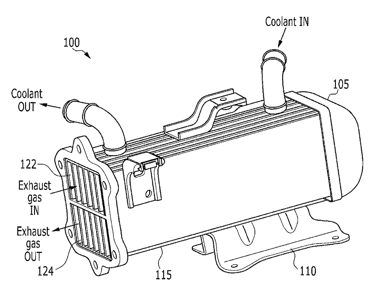
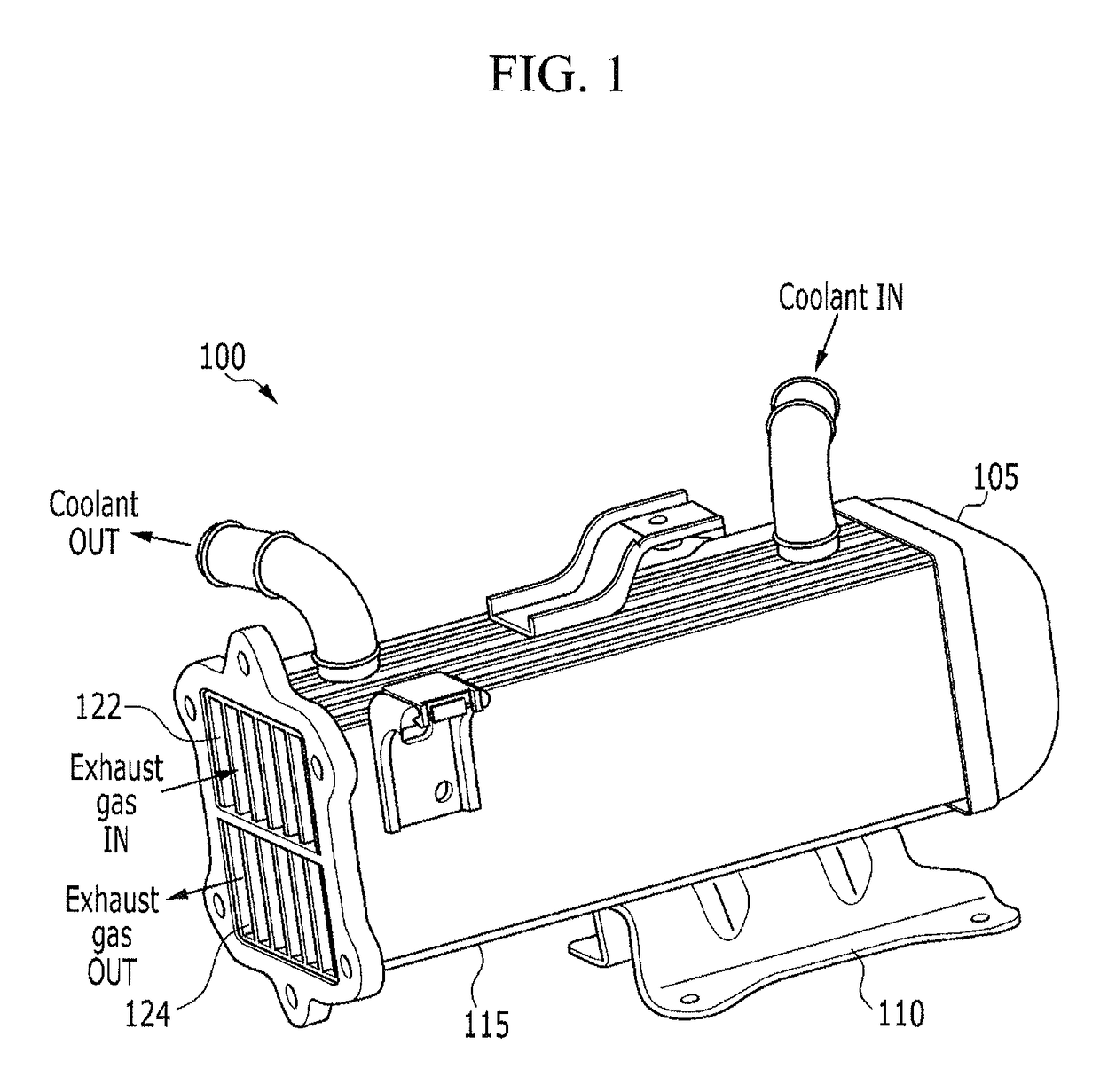
[0036]FIG. 1 is a perspective view of a water-cooled EGR cooler according to an exemplary embodiment of the present invention.
[0037]Referring to FIG. 1, an EGR cooler 100 includes a housing 115, a mounting flange 110, and a ‘U’-shaped flange 105 as major components.
[0038]A coolant inlet pipe, into which a coolant flows, is connected to one end portion at an upper side of the housing 115, and a coolant discharge pipe, through which the coolant is discharged, is connected to the other end portion at the upper side of the housing 115.
[0039]A coolant inlet pipe, into which a coolant flows, is connected to one end portion at an upper side of the housing 115, and a coolant discharge pipe, through which the coolant is discharged, is connected to the other end portion at the upper side of the housing 115.
[0040]The ‘U’-shaped flange 105 is mounted on the other end surface of the housing 115, and the ‘U’-shaped flange 105 communicates the upper portion and the lower portion of the housing 115.
[0041]The exhaust gas supplied through the exhaust gas inlet 122 of the housing 115 flows to the upper side of the housing 115, passes through the ‘U’-shaped flange 105, and flows to the lower side of the housing 115, and is joined to an intake line through the exhaust gas outlet 124. Furthermore, the mounting flange 110 fixes the housing 115 to one side of an engine.
[0042]In an exemplary embodiment of the present invention, the drawings are illustrated for enhancing of understanding of the contents, and when there is no special comment, an upper, a lower, left and right directions may be different from the actual directions.
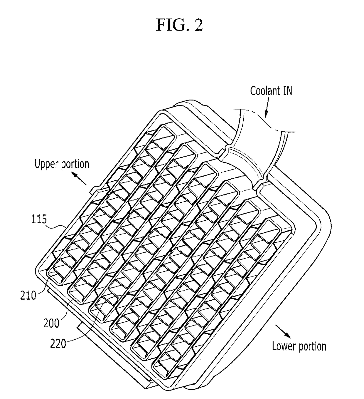
[0043]FIG. 2 is a perspective view of a cross-section of the water-cooled EGR cooler according to an exemplary embodiment of the present invention.
[0044]Referring to FIG. 2, in the EGR cooler 100, tubes 200, pins 210, and supporters 220 are disposed inside the housing 115.
[0045]The tubes 200 have a flat shape and extend in a longitudinal direction, and in which exhaust gas passes. Furthermore, the tubes 200 are disposed at a predetermined interval.
[0046]The supporters 220 are located between the tubes 200. The supporters 220 maintain a predetermined interval between the tubes 200, and form a path, in which the coolant flows, between the tubes 200.
[0047]Furthermore, the pin 210 is disposed inside the tube 200, and the pin 210 is bent in a zig-zag shape, and an external surface of the pin 210 is brazed and in contact with an internal surface of the tube 200.
[0048]The tube 200 has a structure that a coolant flows into an external side of the tube 200, and the pin 210 disposed at the internal side of the tube 200 improves efficiency of heat exchange between the coolant and the EGR gas.
[0049]Regarding manufacturing order and method of a water-cooled exhaust gas recirculation (EGR) cooler according to an exemplary embodiment of the present invention are described referring to FIG. 4 and FIG. 3.
[0050]FIG. 4 is a cross-sectional view illustrating manufacturing order of a water-cooled EGR cooler according to an exemplary embodiment of the present invention.
[0051]Referring to (a) of FIG. 4, the tubes 200 are formed as thin and long pipe shape by bending one sheet, and confront portion 405 are formed by putting cut surfaces of both side edge portions of the sheet opposite to each other. Here, the confront portion 405 is formed at an upper side of the tubes 200.
[0052]Referring to (b) of FIG. 4, the gas passage 465 is formed internal to the tubes 200, and the pins 210 are inserted internal to the gas passage 465.
[0053]The pins 210 are formed by bending one sheet in a zig-zag shape, and of which upper and lower surfaces contact with internal to upper and lower surfaces of the tubes 200. Here, the portions that the pins 210 and the tubes 200 contact with each other cover the confront portion 405.
[0054]Referring to (c) of FIG. 4, the confront portion 405 is bonded by irradiating laser 400 along the confront portion 405 by use of the laser irradiator 410, and simultaneously the tubes 200 and the pins 210 are bonded with each other, therefore the tube bonded portion 440 is formed.
[0055]Referring to (d) of FIG. 4, the water-cooled EGR cooler includes tubes 200, pins 210, supporters 220, a gas passage 465, a supporter bonded portion 450, and a tube bonded portion 300.
[0056]The supporters 220 are disposed between the tubes 200, and one side of outside surface of the supporters 220 covers the tube bonded portion 440. Here, the supporters 220 and the tubes 200 are bonded with each other by brazing welding to form the supporter bonded portion 450 by heating the supporters 220 and the tubes 200 up to brazing temperature.
[0057]FIG. 3 is a flow-chart illustrating manufacturing method of a water-cooled EGR cooler according to an exemplary embodiment of the present invention.
[0058]Referring to FIG. 3, S300 is a step of forming tubes 200. One sheet is bent to be formed at the tubes 200 having a thin and wide pipe shape. Here, the confront portion 405 of which opposite cut surface formed at both end portions of the sheet is formed at the tubes 200, and the sheet may include aluminum.
[0059]S310 is a step of inserting pins 210. One sheet is bent in a zig-zag shape, and the bent pins 210 are inserted into inside of the tubes 200.
[0060]S320 is a step of welding the tubes 200 and the pins 210. The confront portion 405 of the tubes 200 is welded by use of a laser, and simultaneously the tubes 200 and the pins 210 are bonded with each other.
[0061]S330 is a step of supporter assembling, in a state that the tubes 200 and the pins 210 are bonded with each other by laser, the supporters 220 are located between the tubes 200.
[0062]S340 is a step of brazing bonding, the tubes 200 and the supporters 220 that the pins 210 are bonded with are heated to brazing temperature, so that the tubes 200 and the supporters 220 are bonded with each other by brazing welding.
[0063]Furthermore, in an exemplary embodiment of the present invention, referring to FIG. 4(a) again, the confront portion 405 is formed on the tubes 200, and like FIG. 4(c), the laser is irradiated to the tubes 200 to form the tube bonded portion 440, and the tube bonded portion 440 is formed on the upper side of the tubes 200.
[0064]Accordingly, the condensate water in the tubes 200 flows along the lower portion of inside the tubes 200, therefore the tube bonded portion 440 formed on the upper portion of inside the tubes 200 may not be corroded. Furthermore, the bonded portion is formed in duplication by the tube bonded portion 440 and the supporter bonded portion 450, therefore the corrosion resistivity may be more improved.
[0065]For convenience in explanation and accurate definition in the appended claims, the terms “upper”, “lower”, “internal”, “outer”, “up”, “down”, “upper”, “lower”, “upwards”, “downwards”, “front”, “rear”, “back”, “inside”, “outside”, “inwardly”, “outwardly”, “internal”, “external”, “internal”, “outer”, “forwards”, and “backwards” are used to describe features of the exemplary embodiments with reference to the positions of such features as displayed in the figures.
[0066]The foregoing descriptions of specific exemplary embodiments of the present invention have been presented for purposes of illustration and description. They are not intended to be exhaustive or to limit the invention to the precise forms disclosed, and obviously many modifications and variations are possible in light of the above teachings. The exemplary embodiments were chosen and described to explain certain principles of the invention and their practical application, to enable others skilled in the art to make and utilize various exemplary embodiments of the present invention, as well as various alternatives and modifications thereof. It is intended that the scope of the invention be defined by the Claims appended hereto and their equivalents.
PUM


Description & Claims & Application Information
We can also present the details of the Description, Claims and Application information to help users get a comprehensive understanding of the technical details of the patent, such as background art, summary of invention, brief description of drawings, description of embodiments, and other original content. On the other hand, users can also determine the specific scope of protection of the technology through the list of claims; as well as understand the changes in the life cycle of the technology with the presentation of the patent timeline. Login to view more.