Condensation trap for charge air cooler

a charge air cooler and condensate trap technology, applied in the field of charge air coolers, can solve the problems of loss of torque and engine speed, incomplete combustion of fuel, engine misfire, etc., and achieve the effect of reducing the amount of condensate reaching the combustion chamber

Active Publication Date: 2011-04-28
FORD GLOBAL TECH LLC
View PDF31 Cites 111 Cited by
  • Summary
  • Abstract
  • Description
  • Claims
  • Application Information

AI Technical Summary

Benefits of technology

[0005]In one example, the condensate may be released slowly at a rate which is not detrimental to engine operation. For example, during a transient high load engine condition such as a hard acceleration, the condensate may be temporarily stored and released in the direction of airflow to the outlet du

Problems solved by technology

During conditions such as a hard vehicle acceleration, these water droplets may be blown out of the charge air cooler and into the combustion chambers of the engine resulting in engine misfire, loss of torque and engine speed, and incompletely burned fuel, for example.
Such a system may

Method used


Image

  • Condensation trap for charge air cooler
  • Condensation trap for charge air cooler
  • Condensation trap for charge air cooler

Examples


Embodiment Construction

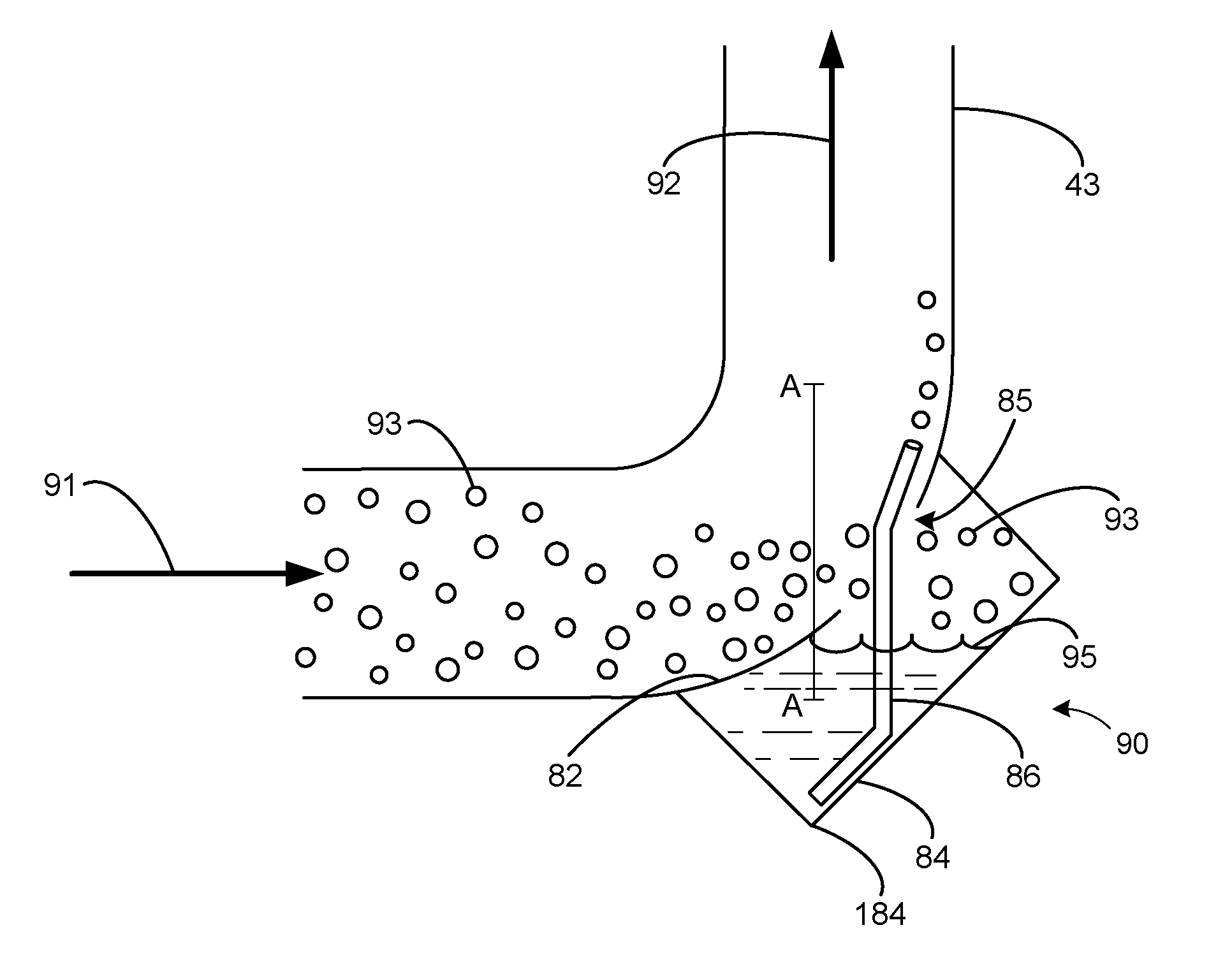
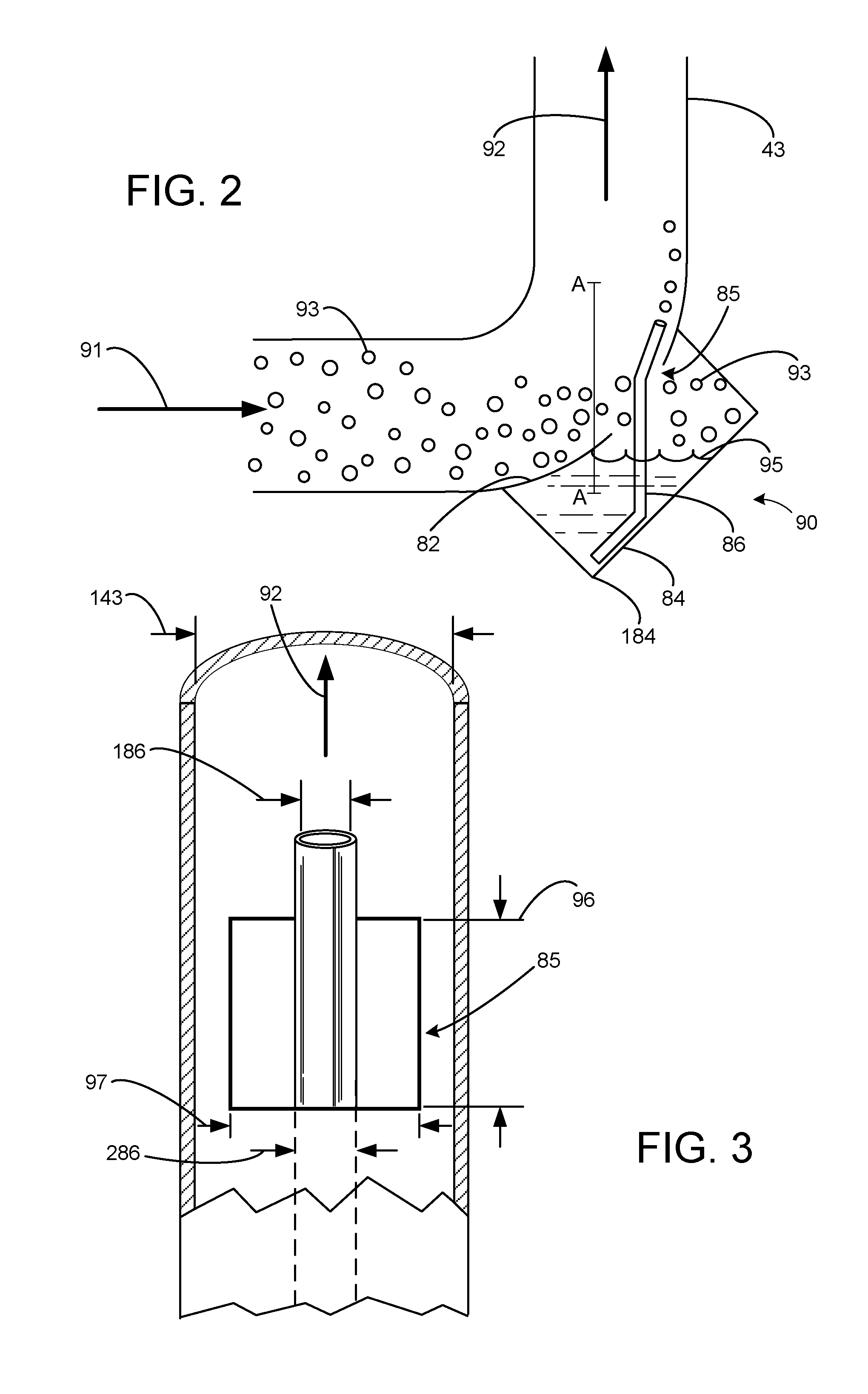
[0011]The following description relates to embodiments of a condensation trap with a charge air cooler in a turbocharged engine for reducing the rate at which condensation enters the combustion chambers of the engine. The condensation trap may be coupled to a bend in an outlet duct, and airflow in the outlet duct may be in communication with the condensation trap via an opening in an outside surface of the bend of the outlet duct. The bend in the outlet duct may encourage water droplets (e.g., condensate) in the airflow to enter the condensation trap. Furthermore, the condensation trap may comprise a reservoir for collecting the condensate and a tube for releasing the condensate back to the outlet duct. Based on engine operating conditions, the collected condensate may be temporarily stored in the reservoir to a greater extent under some operating conditions as compared to others. For example, during transient high load engine conditions when a greater amount of condensate is discha...


PUM


Abstract

Various systems and methods are described for a charge air cooler coupled to an engine. One example method comprises collecting condensate discharged from the cooler in a condensation trap coupled to an outside surface of a bend in an outlet duct of the cooler; during a first condition, temporarily storing the condensate in a reservoir of the condensation trap; and, during first and second conditions, releasing the condensate to the outlet duct in a direction of airflow via a tube.

Description

TECHNICAL FIELD[0001]The present application relates generally to a charge air cooler coupled to an intake manifold of a turbocharged engine in a motor vehicle.BACKGROUND AND SUMMARY[0002]Turbocharged and supercharged engines may be configured to compress ambient air entering the engine in order to increase power. Because compression of the air may cause an increase in temperature of the air, a charge air cooler may be utilized to cool the heated air thereby increasing its density and further increasing the potential power of the engine. If the humidity of the ambient air is high, however, condensation (e.g., water droplets) may form on any internal surface of the charge air cooler that is cooler than the dew point of the compressed air. During conditions such as a hard vehicle acceleration, these water droplets may be blown out of the charge air cooler and into the combustion chambers of the engine resulting in engine misfire, loss of torque and engine speed, and incompletely burne...

Claims


Application Information

Patent Timeline
IPC IPC(8): F02B29/04F25D21/14F02B33/34
CPCF02B29/0468F02B37/18Y02T10/144Y02T10/146F28F17/005Y02T10/12
Inventor PALM, JAMES RAYMOND
Owner FORD GLOBAL TECH LLC
Why Eureka
Try Eureka