Lubricant coating device and image forming apparatus

a technology of lubricant coating and image forming apparatus, which is applied in the direction of coating, optics, instruments, etc., can solve the problems of increasing the difficulty of removing residual toner, affecting the quality of image supporters, and preventing the unevenness of lubricant powders on image supporters. to achieve the effect of preventing the unevenness of lubricant powders

Active Publication Date: 2018-11-15
KONICA MINOLTA INC
View PDF0 Cites 5 Cited by
  • Summary
  • Abstract
  • Description
  • Claims
  • Application Information

AI Technical Summary

Benefits of technology

[0007]The present invention is achieved in view of the above-mentioned problems. Therefore, an object of the present invention is to provide a lubricant coating device and an image forming apparatus that prevent coating unevenness of lubricant powders even in the case where the polarity of the surface potential becomes different depending on the positions of an image supporter.

Problems solved by technology

For this reason, with the smaller size and the spherical shape in toner particles, it becomes more difficult to remove residual toner.
As a result, there is a problem that coating unevenness of the lubricant powders occurs on the image supporter.
Moreover, even in the case where both the lubricant powders charged to the reverse polarity to the charged polarity of the image supporter and the lubricant powders charged to the same polarity with the charged polarity of the image supporter are supplied to the image supporter, in the case where the supply amount of the lubricant powders of each polarity is different from each other, there is also a problem that coating unevenness of the lubricant powders cannot be prevented on the image supporter.

Method used


Image

  • Lubricant coating device and image forming apparatus
  • Lubricant coating device and image forming apparatus
  • Lubricant coating device and image forming apparatus

Examples


example 1

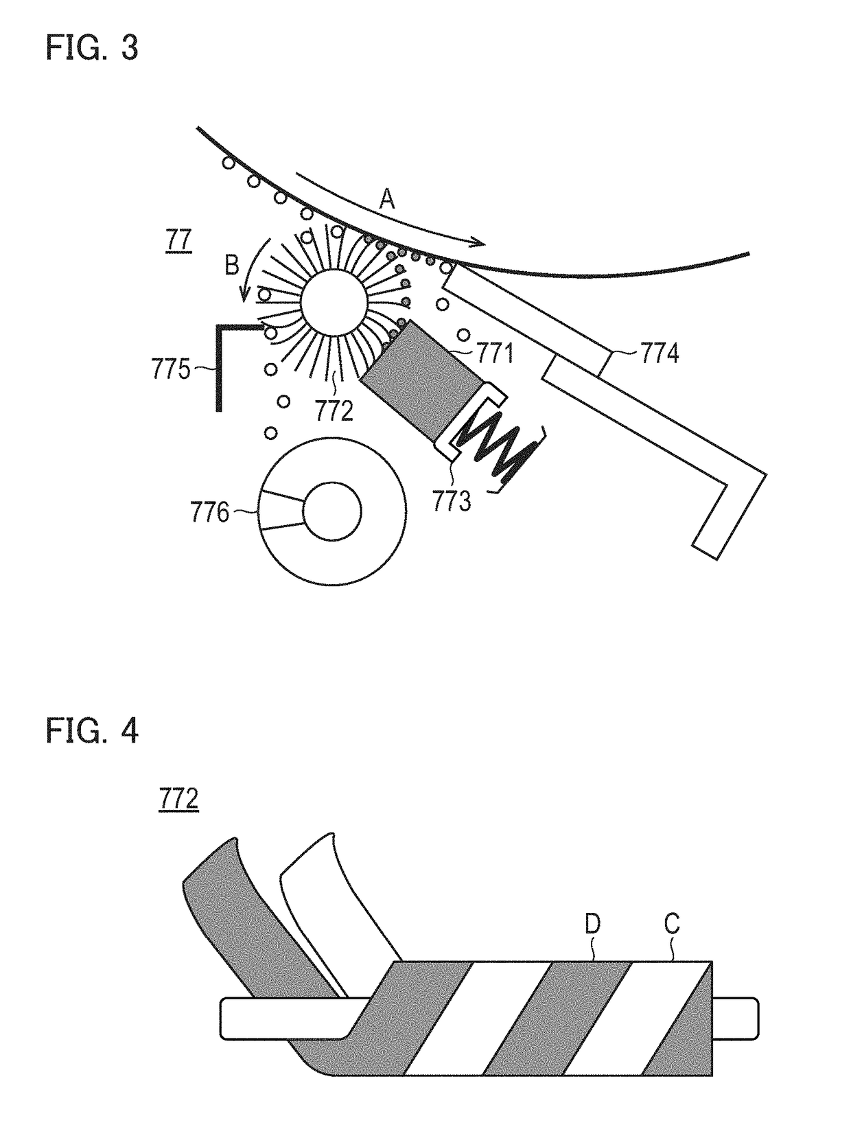
[0095]Nylon fibers and fluororesin fibers were used as brush hair. The fineness of the nylon fibers was set to 3 d, and the fineness of the fluororesin fibers was set to 10 d. The loop bundle of each of the fibers was made into a non-twisted bundle. The loop surface of each of the fibers was set to be vertical to the rotation direction of the coating brush 772. The pushing amount of each of the fibers was set to 1.0 mm, and the implanting density of each of the fibers was set to 180 kF / inch2.

example 2

[0096]Nylon fibers and fluororesin fibers were used as brush hair. The fineness of each of the fibers was set to 3 d. The loop bundle of the nylon fibers was made into a non-twisted bundle, and the loop bundle of the fluororesin fibers was made into a twisted bundle. The loop surface of each of the fibers was set to be vertical to the rotation direction of the coating brush 772. The pushing amount of each of the fibers was set to 1.0 mm, and the implanting density of each of the fibers was set to 180 kF / inch2.

example 3

[0097]Nylon fibers and fluororesin fibers were used as brush hair. The fineness of each of the fibers was set to 3 d, and the loop bundle of each of the fibers was made into a non-twisted bundle. The loop surface of the nylon fibers was set to be parallel to the rotation direction of the coating brush 772, and the loop surface of the fluororesin fibers was set to be vertical to the rotation direction of the coating brush 772. The pushing amount of each of the fibers was set to 1.0 mm, and the implanting density of each of the fibers was set to 180 kF / inch2. In this connection, the term “vertical” means “substantially vertical”, and was set to an angle within ±10 degree with respect to perfect vertical. Moreover, the term “parallel” means “substantially parallel”, and was set to an angle within ±10 degree with respect to perfect parallel.


PUM

PropertyMeasurementUnit
temperatureaaaaaaaaaa
thicknessaaaaaaaaaa
speedaaaaaaaaaa

Abstract

A lubricant coating device preventing coating unevenness of lubricant powders is provided. The lubricant coating device includes a solid lubricant, a coating member and a film shaping member. The coating member in which first fibers composed of a material located on a positive polarity side and second fibers composed of a material located on a negative polarity side, on a triboelectric series with respect to the material of the solid lubricant are implanted, coats lubricant powders scraped off from the solid lubricant onto the image supporter. The film shaping member comes in contact with the image supporter and presses the lubricant powders onto the image supporter, to shape the lubricant powders into a form of a film. A scraping amount of the lubricant powders by the first fibers and a scraping amount of the lubricant powders by the second fibers are set to become substantially identical.

Description

CROSS-REFERENCE TO RELATED APPLICATION[0001]The entire disclosure of Japanese Patent Application No. 2017-094064, filed on May 10, 2017, is incorporated herein by reference in its entirety.BACKGROUND1. Technological Field[0002]The present invention relates to a lubricant coating device and an image forming apparatus.2. Description of the Related Art[0003]Conventionally, in image forming apparatuses using an electrophotographic process, as methods of removing toner (residual toner) remaining on an image supporter such as a photoreceptor after a toner image on the image supporter has been transferred, a method of scraping the residual toner with a cleaning blade has been proposed. On the other hand, in recent years, from viewpoints of making image quality high, techniques to make toner particles small in size and spherical in shape have been advanced. However, as toner particles are made smaller, the adhesion force of the toner particles to the image supporter becomes stronger, and as...

Claims


Application Information

Patent Timeline
Patent Type & Authority Applications(United States)
IPC IPC(8): F16N7/24B05C1/02B05B15/00
CPCF16N7/24B05C1/02B05B15/00F16N15/00G03G21/0094
Inventor AZUMA, YUKIMASA
Owner KONICA MINOLTA INC
Why Eureka
Try Eureka