Automatic coating device for metal plates

An automatic coating, metal sheet technology, applied to the surface coating device, spray device, coating and other directions, can solve the problem of operator mistaken touch, no temperature control measures, poor appearance, etc.

Inactive Publication Date: 2021-10-08
苏州邦得新材料科技有限公司
View PDF0 Cites 3 Cited by
  • Summary
  • Abstract
  • Description
  • Claims
  • Application Information

AI Technical Summary

Problems solved by technology

[0004] Aiming at the deficiencies in the prior art, the present invention provides an automatic coating device for sheet metal, which solves the problem that the automatic coating device for sheet metal currently used is inconvenient to dry the sheet metal to be coated, such as impurities on the surface of the sheet metal. If there is no substance or moisture, it may affect the painting and coating of the metal sheet. At the same time, no anti-mistouch measures are provided for the controller on the spraying equipment, which will easily cause the operator to accidentally touch the button of the processing equipment, resulting in changes in the coating process parameters, affecting The processing quality of the product, in addition, there is no effective temperature control measure in the drying process after coating, it is easy to cause the oven temperature to be too high or the temperature cannot reach the process standard, resulting in poor appearance

Method used


Image

  • Automatic coating device for metal plates
  • Automatic coating device for metal plates
  • Automatic coating device for metal plates

Examples


Embodiment Construction

[0028] The following will clearly and completely describe the technical solutions in the embodiments of the present invention with reference to the accompanying drawings in the embodiments of the present invention. Obviously, the described embodiments are only some, not all, embodiments of the present invention. Based on the embodiments of the present invention, all other embodiments obtained by persons of ordinary skill in the art without making creative efforts belong to the protection scope of the present invention.

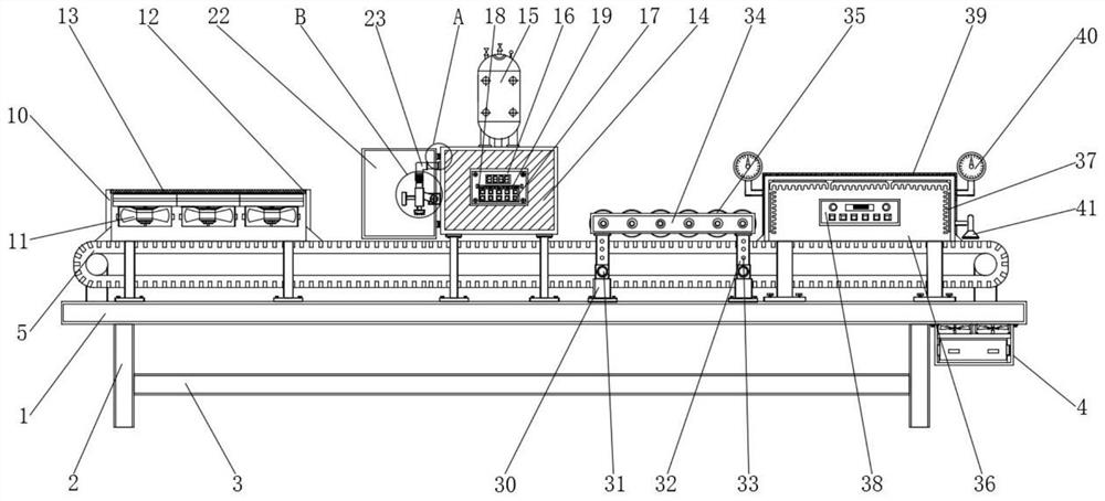
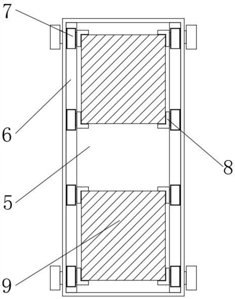
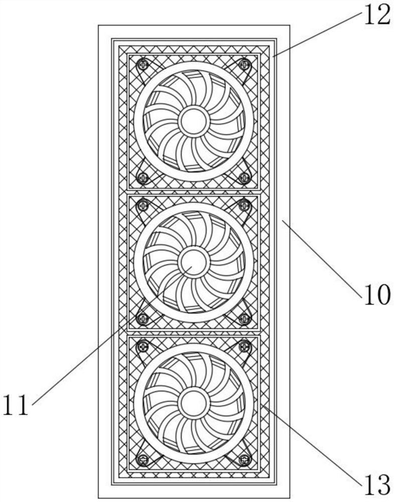
[0029] according to Figure 1-6The shown automatic coating device for sheet metal includes a processing table 1 and a dust suction mechanism 4. The bottom end of the processing table 1 is welded with a support column 2, and the outer wall of the support column 2 is welded with a material placement plate 3, and the dust suction mechanism 4 screws are connected to the bottom of the processing table 1, the surface of the processing table 1 is provided with a conv...


PUM


Abstract

The invention discloses an automatic coating device for metal plates, and particularly relates to the related technical field of metal plate machining. The automatic coating device for the metal plates comprises a machining table and a dust collection mechanism, a supporting column is welded to the bottom end of the machining table, a material placing plate is welded to the outer wall of the supporting column, the dust collection mechanism is connected to the bottom end of the machining table through screws, a thermometer is arranged at the top end of the outer wall of a drying oven, and a brush is arranged at the bottom end of the outer wall of the drying oven. Through the arrangement of an air blower, dust and water on the surface of the to-be-coated metal plates can be conveniently cleaned through a blowing fan in the air blower before the to-be-coated metal plates is coated, and uneven coating caused by dust and water remaining on the surface of the to-be-coated metal plates is avoided; and meanwhile, through a magnetic attraction strip and a dustproof net arranged on the surface of the top end of the air blower, external dust can be prevented from being sucked into the air blower when the air blower works, and cleanliness of the surfaces of the to-be-coated metal plates is guaranteed.

Description

technical field [0001] The invention relates to the related technical field of sheet metal processing, and more specifically, the invention relates to an automatic coating device for sheet metal. Background technique [0002] Metal materials refer to materials with luster, ductility, easy conduction, heat transfer and other properties. They are generally divided into ferrous metals and non-ferrous metals. Ferrous metals include iron, chromium, manganese, etc. Among them, steel is the basic structural material, called As the backbone of the industry, due to the advancement of science and technology, the wide application of various new chemical materials and new non-metallic materials, the substitutes for steel are increasing, and the demand for steel is relatively declining. It is difficult to replace the dominant position in the metal sheet. Metal materials can also be made into sheet metal. In order to process the sheet metal, the surface of the sheet metal is sprayed and c...

Claims


Application Information

Patent Timeline
Patent Type & Authority Applications(China)
IPC IPC(8): B05B12/00B05B12/36B05B16/20B05B13/02B05D3/02B08B5/02B08B1/00B08B5/04
CPCB05B12/002B05B12/36B05B16/20B05B13/0221B05D3/0254B08B5/023B08B1/002B08B5/043
Inventor 苗珍录
Owner 苏州邦得新材料科技有限公司
Why Eureka
Try Eureka