Contact probe and inspection jig

Inactive Publication Date: 2018-11-22
YOKOWO CO LTD
View PDF0 Cites 3 Cited by
  • Summary
  • Abstract
  • Description
  • Claims
  • Application Information

AI Technical Summary

Benefits of technology

The patent is related to a contact probe and an inspection jig that can perform a scrub operation. The technical effects of this patent are to reduce the risk of strength reduction of the plunger and make the working operation of the tube easier.

Problems solved by technology

Thus, the small-diameter intermediate portion may become insufficient in strength, when the diameter of the plunger is reduced according to a diameter reduction of the contact probe.
Furthermore, in the structure of JP-U-03-099364, since it is necessary to increase a thickness of a tip portion of the tube to which the plunger is to come into contact, a working operation of the tip portion of the tube would become difficult.

Method used


Image

  • Contact probe and inspection jig
  • Contact probe and inspection jig
  • Contact probe and inspection jig

Examples


embodiment 1

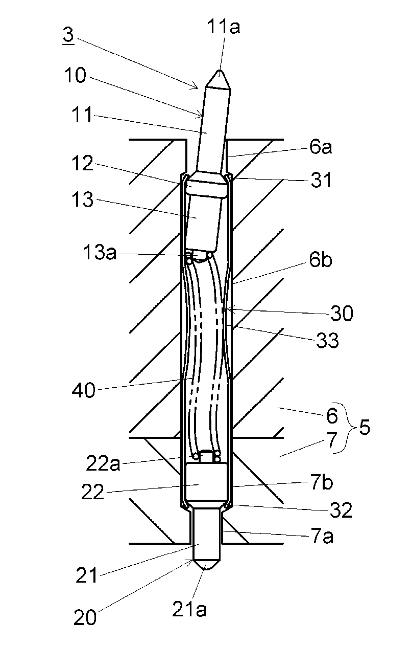
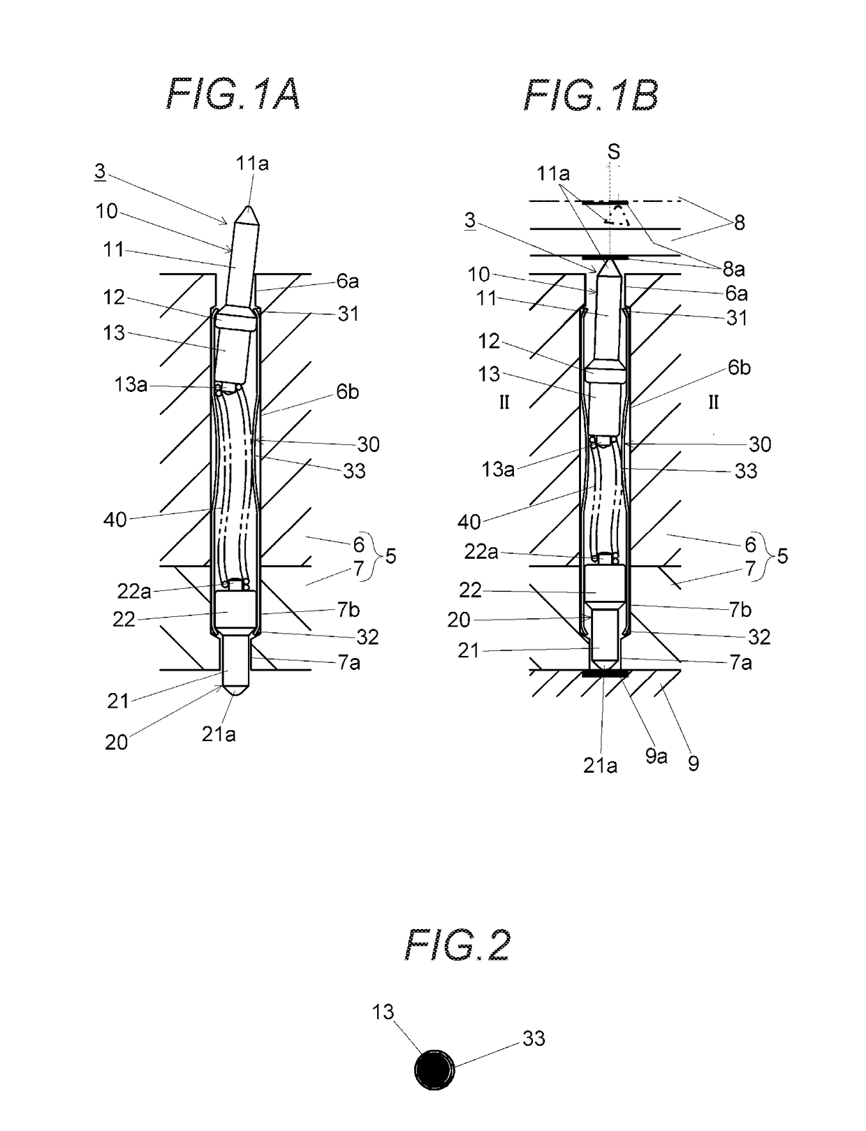
[0025]FIG. 1A is a sectional view of an inspection jig 1A according to a first embodiment, and FIG. 1B is a sectional view showing how an inspection is conducted using the inspection jig 1A. The inspection jig 1A is equipped with a contact probe 3 and an electrically insulative socket 5 which holds the contact probe 3 penetrating through it. Although in the illustrated example only one contact probe 3 is supported by the socket 5, plural contact probes 3 may be supported by the socket 5. The socket 5 is formed by combining a first socket 6 and a second socket 7 together and screwing them on each other into an integral body. A small-diameter hole 6a and a large-diameter hole 6b of the first socket 6 and a small-diameter hole 7a and a large-diameter hole 7b of the second socket 7 constitute a through-hole in which the contact probe 3 is set.

[0026]The contact probe 3 has a first plunger 10, a second plunger 20, a tube 30, and a spring 40. The first plunger 10 is a component for connect...

embodiment 2

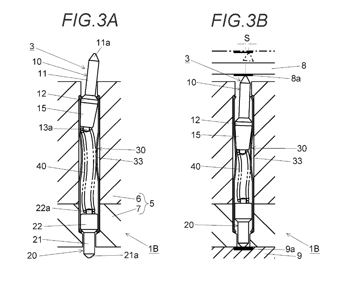
[0050]FIG. 3A is a sectional view of an inspection jig 1B according to a second embodiment.FIG. 3B is a sectional view showing how an inspection is conducted using the inspection jig 1B. The inspection jig 1B according to this embodiment is the same as the inspection jig 1A according to the first embodiment except that the base-side cylinder portion 13 of the first plunger 10 is replaced by a base-side truncated-cone portion 15. The outer circumferential surface of the base-side truncated-cone portion 15 is part of the side surface of a cone, and hence its outer diameter decreases as the position goes from the side of the flange portion 12 to the side of the spring 40. The outer diameter of the end of the base-side truncated-cone portion 15 on the side of the flange portion 12 is the same as that of the flange portion 12. This embodiment would provide the same advantages as the first embodiment.

embodiment 3

[0051]FIG. 4A is a sectional view of an inspection jig 1C according to a third embodiment. FIG. 4B is a sectional view showing how an inspection is conducted using the inspection jig 1C. The inspection jig 1C according to this embodiment is the same as the inspection jig 1A according to the first embodiment except that the projection 13a formed on the base surface of the base-side cylinder portion 13 of the first plunger 10 is absent and the base surface (slant surface 13b) is inclined with respect to the longitudinal direction of the first plunger 10 and that the two end surfaces of the spring 40 being in a free state are flat surfaces that are perpendicular to the longitudinal direction of the spring 40. This embodiment would provide the same advantages as the first embodiment.


PUM


Abstract

A contact probe includes a tube which is electrically conductive, a plunger which is electrically conductive and disposed in the tube at one end of the tube, and a spring which is disposed in the tube and urges the plunger in a projection direction. The tube includes a slant portion on an inner circumferential surface of the tube. The slant portion is inclined with respect to an axial direction of the tube. A base portion comes into contact with the slant portion and an inclination of the plunger varies, when the plunger retracts.

Description

CROSS-REFERENCES TO RELATED APPLICATIONS[0001]This patent application is based on and claims priority from Japanese Patent Application No. 2017-097860 filed on May 17, 2017, the entire contents of which are incorporated herein by reference.BACKGROUND1. Field of the Invention[0002]The present invention relates to a contact probe used for inspecting a measurement target device such as a semiconductor integrated circuit and an inspection jig including the contact probe.2. Description of Related Art[0003]JP-U-03-099364 discloses a contact probe including a tube and a plunger movable parallel with an axial direction of the tube.[0004]In the structure of JP-U-03-099364, the plunger includes a small-diameter intermediate portion between a tip portion and a base portion. The small-diameter intermediate portion is required to have a length over a stroke length or more of the plunger. Thus, the small-diameter intermediate portion may become insufficient in strength, when the diameter of the p...

Claims


Application Information

Patent Timeline
IPC IPC(8): G01R1/067G01R31/28G01R31/26G01R1/04H01R13/24
CPCG01R1/06722G01R31/2886G01R31/26G01R1/0433H01R13/2421G01R1/06794G01R1/0441G01R1/06733
Inventor YAMAMOTO, TSUGIO
Owner YOKOWO CO LTD
Why Eureka
Try Eureka