
Automated method of generalized building automation from atomic physical models and control loops thereof

Active Publication Date: 2018-11-22
PASSIVELOGIC INC
View PDF7 Cites 9 Cited by
  • Summary
  • Abstract
  • Description
  • Claims
  • Application Information

AI Technical Summary

Benefits of technology

The patent aims to offer a model-based approach for controlling building automation systems, which will enable predictive estimation of system state and improve comfort, performance, and efficiency. It also utilizes a reasoning system approach to make intelligent use of reasoned decisions as heuristics. Additionally, it enhances user feedback and system transparency. In summary, the patent ensures better performance and efficiency of building automation systems by providing predictive analysis and utilizing machine intelligence.

Problems solved by technology

Such systems are capable of flexible control of various building parameters, but are generally time and labor intensive to install.
The enormity of such a task in even modestly sized buildings makes building automation systems typically expensive, hard to adapt to varying circumstances and setups, and often leads to less than optimal performance.
The model-free approach, while simple to implement, becomes quite difficult to manage and optimize as the complexity of the system increases.
It also lacks the inherent self-knowledge to provide new approaches to programming, such as model-driven graphical programming, or to govern the interconnections between components and sub-system synergistics.
Physical model based approaches are relatively new in this space, and have only recently become feasible due to advances in embedded system CPU performance.
While this work was a successful demonstration of the potential impact of physical models on control, the scope was limited to a predetermined system configuration under investigation without any ad hoc construction, GUI inputs, or model evolution.
Despite the efforts to improve building automation systems, no solutions exist that completely address the aforementioned challenges with building automation systems.
Nor do solutions exist to provide physical model-based control without relying on hand-constructed scenarios, human-in-the-loop, human supervision, and / or limiting the scope of the controlled systems to a known set of topologies.

Method used


Image

  • Automated method of generalized building automation from atomic physical models and control loops thereof
  • Automated method of generalized building automation from atomic physical models and control loops thereof
  • Automated method of generalized building automation from atomic physical models and control loops thereof

Examples


Embodiment Construction

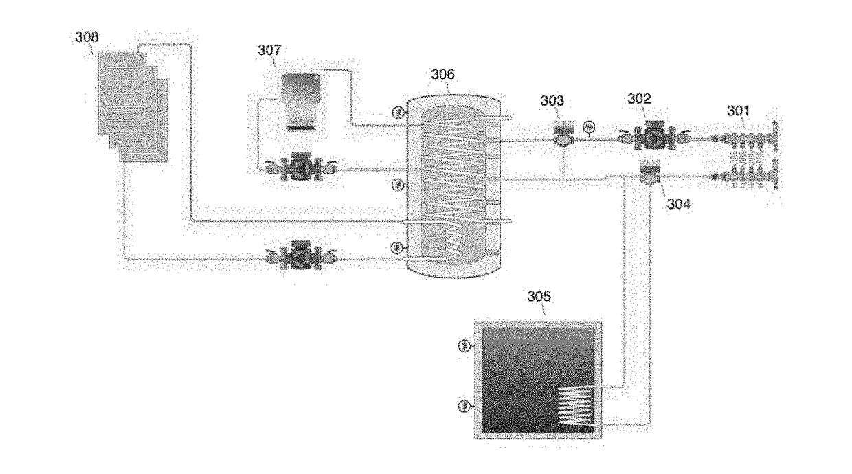
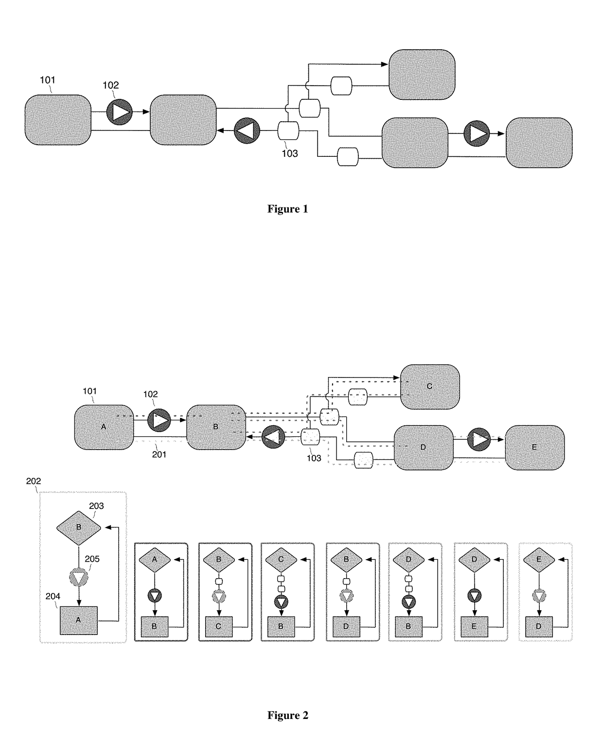
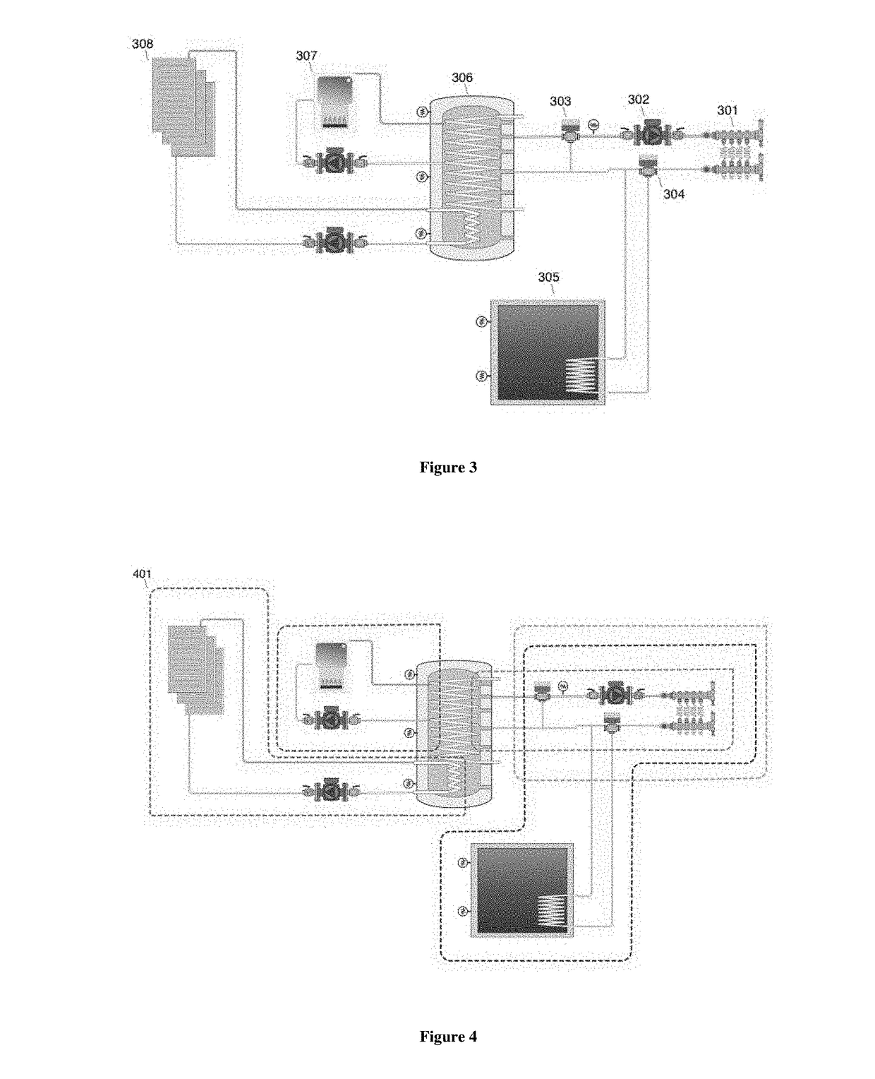
[0029]Explanation will be made below with reference to the aforementioned figures for illustrative embodiments concerning the present disclosure.

[0030]In its fundamental form, a building control system contains a control loop, consisting of a controller, a system under control, and sensors for gathering data about the state of the controlled system. The controller makes decisions based on the sensor feedback. The control decisions are then applied to the controlled system. The resulting effects on the system are monitored by the sensors. One embodiment of a building control loop comprises an air temperature sensor, a thermostat controller, and a controlled system comprising a furnace, fan, air conditioner, and building. In this embodiment, the furnace and air conditioner are sources, the fan is a transport, and the building is an energy sink.

[0031]A controller may contain a simulation engine. The simulation engine allows the system to predict the outcome of any possible control acti...


PUM


Abstract

Disclosed is a system and method for classifying units of control and concomitant model units from a larger physical system model. The system enables model-based simulation of decoupled system units for improved simulation efficiency. Further, the system allows for automated reasoning about the classification of said units, producing both machine-interpretable and human-readable, natural language descriptions of the decisions and reasons for said decisions made during the classification process, for use in heuristics and user feedback.

Description

FIELD[0001]The present disclosure relates to the control of building systems using automated means. More specifically, the present disclosure relates to an automated method of identifying and classifying individual control units from a physical system model.BACKGROUND[0002]Buildings contain a varied and complex set of systems for managing and maintaining the building environment. Building automation systems are used to automate the control of many separate systems, such as those used for lighting, climate, security, entertainment, etc. Building automation systems can perform a number of functions, such as automation of equipment scheduling, monitoring of building parameters, optimization of resource consumption, event or alarm reporting and handling, as well as many others. Automated systems in buildings optimize performance, for example reducing cost and increasing convenience.[0003]A component of the building automation system is the control system (also called control loop, contr...

Claims


Application Information

Patent Timeline
IPC IPC(8): G05B13/04
CPCG05B13/048G05B15/02G05B2219/2642
Inventor HARVEY, TROY AARON
Owner PASSIVELOGIC INC
Learn More