
Flange joining structure

a technology of joining structure and flange, which is applied in the direction of flanged joints, pipe joints, sealing arrangements for engines, etc., can solve the problems of inability to maintain a sufficient sealing property, and achieve the effects of preventing cracks, facilitating breakage, and stabilizing the behavior of gaskets

Inactive Publication Date: 2018-11-29
HONDA MOTOR CO LTD
View PDF11 Cites 8 Cited by
  • Summary
  • Abstract
  • Description
  • Claims
  • Application Information

AI Technical Summary

Benefits of technology

The patent text describes a flange joining structure that can maintain a sealing property even when high-temperature exhaust gas flows through it. This is achieved by using a cylinder head with multiple bifurcated pipelines and collecting pipelines that guide the exhaust gas to the flange. This structure reduces the number of parts and enables a downsized device. Additionally, the flange joining structure enhances the sealing property, making it suitable for use in high-temperature exhaust gas flows.

Problems solved by technology

Hei 10-169456 may be incapable of maintaining a sufficient sealing property because of the heat of exhaust gas.

Method used


Image

  • Flange joining structure
  • Flange joining structure
  • Flange joining structure

Examples


Embodiment Construction

[0028]Hereinafter, an embodiment of the present disclosure will be described with reference to the drawings.

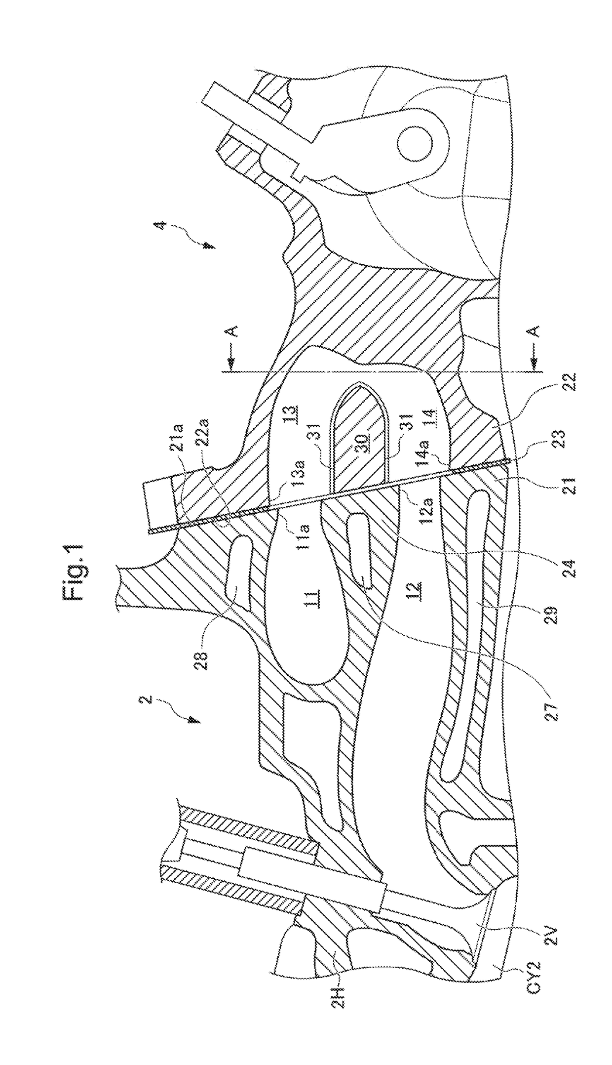
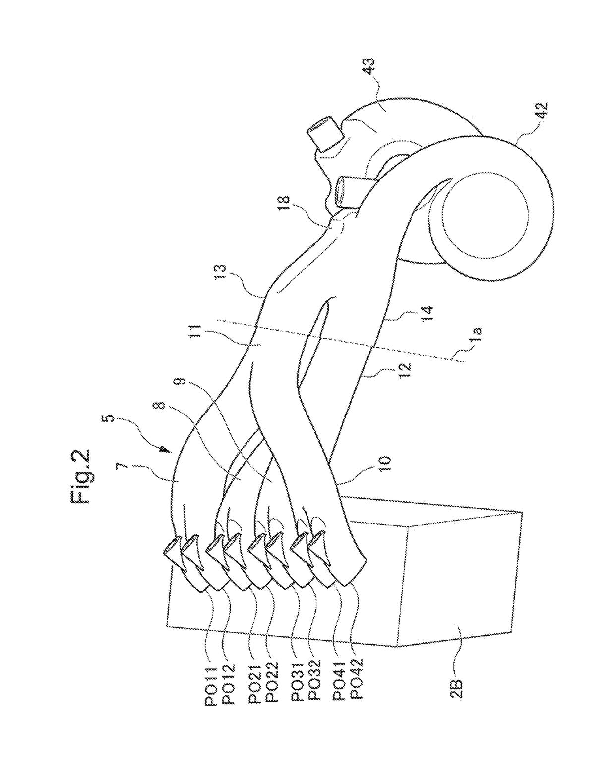
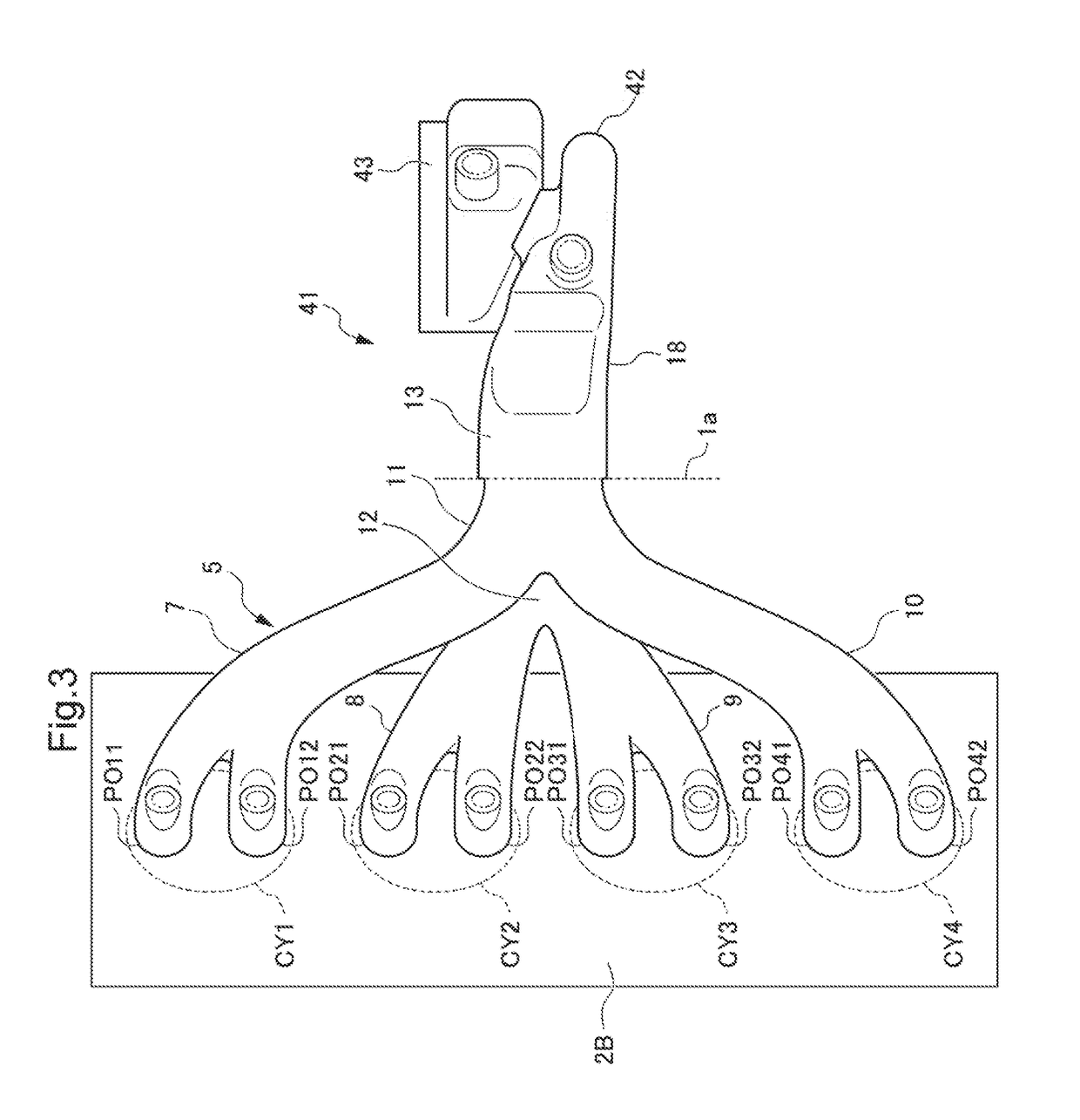
[0029]FIG. 1 is a cross-sectional view of an internal combustion engine 2 and a turbine housing 4 that are joined by applying a flange joining structure of the embodiment of the present disclosure. As will be described later with reference to FIG. 2 and other drawings, the internal combustion engine 2 is an inline-four engine configured by arranging multiple, or more specifically, four cylinders in series. FIG. 1 is a cross-sectional view including a second cylinder CY2 of the internal combustion engine 2 and the turbine housing 4.

[0030]The internal combustion engine 2 is configured by combining a cylinder block 2B in which multiple cylinders including the second cylinder CY2 are formed, and a cylinder head 2H provided with parts such as multiple exhaust passages that allow passage of exhaust gas discharged from combustion chambers in the cylinders, and exhaust valves 2V. The ...


PUM


Abstract

A flange joining structure comprises flanges of a cylinder head of an internal combustion engine and a turbine housing joined through a gasket. The flange of cylinder head has, in an end face thereof, end parts of a first collecting exhaust pipe and a second collecting exhaust pipe; the flange of turbine housing has, in an end face thereof, end parts of a first pre-merge exhaust pipe and a second pre-merge exhaust pipe corresponding to the end parts of the first collecting exhaust pipe and the second collecting exhaust pipe; and the gasket has, on a face on the cylinder head side, a bead formed into an edge-rounded rectangle having a straight part shorter than the radius of curvature thereof, and surrounding the end parts of the first collecting exhaust pipe and the second collecting exhaust pipe.

Description

CROSS REFERENCES TO RELATED APPLICATIONS[0001]The present application claims priority under 35 U.S.C. § 119 to Japanese Patent Application No. 2017-101466, filed May 23, 2017, entitled “ FLANGE JOINING STRUCTURE.” The contents of this application are incorporated herein by reference in their entirety.TECHNICAL FIELD[0002]The present disclosure relates to a flange joining structure. More specifically, the disclosure relates to a flange joining structure in which a flange formed in a cylinder head of an internal combustion engine and a flange formed in an exhaust member are connected through a plate-like gasket.BACKGROUND[0003]Heretofore, a gasket has been provided between a flange formed in a cylinder head of an internal combustion engine and a flange formed in an exhaust member of an exhaust pipe, a turbine housing, or the like, to prevent leakage of exhaust gas between the cylinder head and exhaust member. For example, Japanese Patent Application Publication No. Hei 10-169456 discl...

Claims


Application Information

Patent Timeline
Patent Type & Authority Applications(United States)
IPC IPC(8): F01N13/18F16L23/16
CPCF01N13/1827F01N13/1855F16L23/16F01N2450/24F02F11/002F01N13/001
Inventor HIDESHIMA, MINORUYAMAMOTO, NORITAKA
Owner HONDA MOTOR CO LTD
Learn More