Rotary compressor

a compressor and rotary technology, applied in the direction of machines/engines, liquid fuel engines, positive displacement liquid engines, etc., can solve the problems of increasing material cost and space utilization, reducing the service life of the compressor, and restricting the suction port area, so as to improve the compressor performance, and minimize the effect of flow loss

Active Publication Date: 2018-11-29
LG ELECTRONICS INC
View PDF6 Cites 1 Cited by
  • Summary
  • Abstract
  • Description
  • Claims
  • Application Information

AI Technical Summary

Benefits of technology

[0033]In the vane rotary compressor according to the present disclosure, as the suction pipe is connected to the casing and the suction passage is formed in the main bearing, an increased area of the suction port may be secured to prevent suction loss in advance, thereby improving the performance of the compressor.
[0034]Furthermore, in case of a low-pressure type in which the inner space of the casing forms a suction pressure, a suction guide pipe may be connected between the suction pipe and the suction passage to minimize a flow loss of refrigerant being sucked into the compression chamber, thereby improving the compressor performance.
[0035]In addition, as the suction passage or the suction port is extended in the direction of the suction start point, a suction area at the suction start point may be secured to prevent the suction start point from being delayed while at the same time preventing the suction completion point from being shifted backward, preventing the compression duration from being shortened.

Problems solved by technology

On the contrary, in the latter case, since an inner space of the casing is used as a type of accumulating space, it is not necessary to provide a separate accumulator, thereby increasing the material cost and space utilization.
However, in a vane rotary compressor in the related art as described above, the suction port is formed in a front side block corresponding to one side surface in an axial direction of the compression chamber, there was a limitation that an area of the suction port is restricted.
It may cause a problem that the suction loss is increased as a flow resistance is increased with respect to refrigerant being sucked into the suction port, thereby reducing the performance of the compressor.
In particular, since the suction area is restrictive during high-speed operation, there is a limitation in applying to a large-capacity model.
Furthermore, in the case of the prior art described above, in case of a high-pressure type in which an inner space of the casing forms a discharge pressure, or a low-pressure type in which the inner space of the casing forms a suction pressure, refrigerant being sucked into the inner space of the casing may flow in the inner space of the casing without being directly sucked into the suction port to cause a type of flow loss, thereby further increasing suction loss.
Besides, in case of the related art described above, as the suction port is formed in a regular shape and the suction port is formed away from the suction start point, the suction start time is delayed, and due to this, the compression performance due to the suction loss may be deteriorated.
In consideration of this, when the suction completion point is shifted backward with respect to the compression advancing direction, the compression duration may be shortened, thereby causing compression loss while generating over-compression.

Method used


Image

  • Rotary compressor
  • Rotary compressor
  • Rotary compressor

Examples


Embodiment Construction

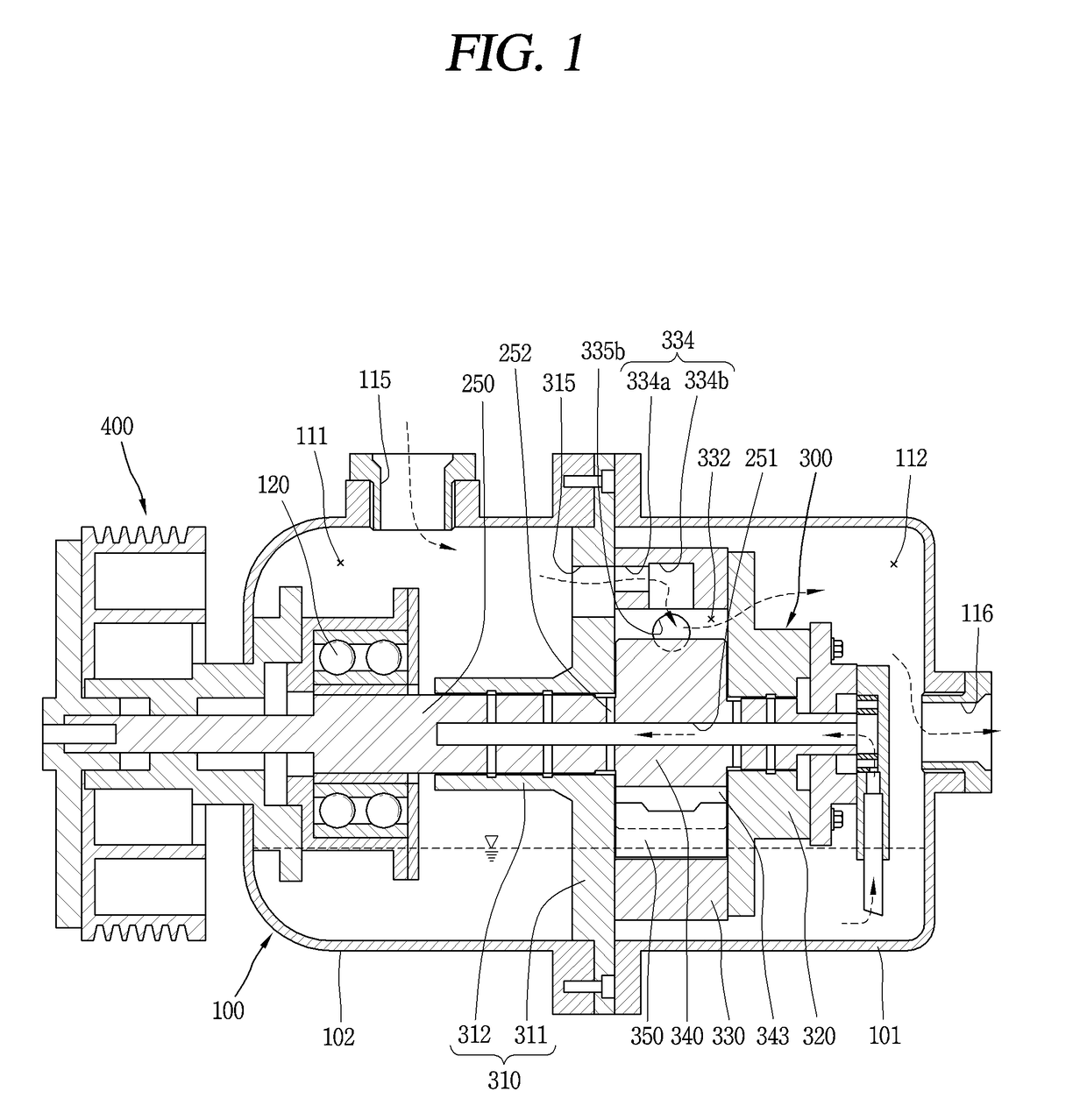
[0047]Hereinafter, a rotary compressor according to the present disclosure will be described in detail with reference to an embodiment illustrated in the accompanying drawings. For reference, the present disclosure is applied to a type of low-pressure vane rotary compressor in which the inner space of the casing forms a suction pressure, and may be applicable to both longitudinal and transverse types. Furthermore, the present disclosure may be applicable to both a closed type in which an electric motor unit and a compression unit are provided together inside the casing, and an open type in which the electric motor unit is provided outside the casing. However, in the present embodiment, a transverse open type vane rotary compressor is taken as a representative example for the sake of convenience. In addition, a representative example of a vane rotary compressor will be described and then another type of vane rotary compressor will be additionally described.

[0048]FIG. 1 is a longitudi...


PUM


Abstract

A rotary compressor includes a cylinder that is coupled to an inner space of a casing and that defines a compression space, a first bearing and a second bearing located at upper and lower sides of the cylinder, a roller disposed eccentrically with respect to an inner circumferential surface of the cylinder to vary a volume of the compression space based on rotation, and a vane inserted into the roller to rotate together with the roller, and drawn out toward the inner circumferential surface of the cylinder during the rotation of the roller to partition the compression space into a plurality of compression chambers. A suction passage communicating with the compression space is defined in the first bearing or the second bearing, and a suction port communicating between the suction passage and the compression space is defined on a side surface of the cylinder.

Description

CROSS-REFERENCE TO RELATED APPLICATIONS[0001]The present disclosure relates to subject matter contained in priority Korean Application No. 10-2017-0065454, filed on May 26, 2017, which are herein expressly incorporated by reference in their entirety.BACKGROUND1. Field[0002]The present disclosure relates to a rotary compressor, and more particularly, to a low-pressure vane rotary compressor.2. Description of the Related Art[0003]A typical rotary compressor is a compressor in which a roller and a vane are in contact with each other to divide a compression space in a cylinder into a suction chamber and a discharge chamber around the vane. In such a typical rotary compressor, the vane performs a linear motion while the roller performs an orbiting motion, and thus the suction chamber and the discharge chamber form a compression chamber having a variable volume (capacity) to suck, compress and discharge refrigerant.[0004]Furthermore, contrary to the typical rotary compressor, a vane rotar...

Claims


Application Information

Patent Timeline
Patent Type & Authority Applications(United States)
IPC IPC(8): F04C18/344F04C29/00F04C29/12
CPCF04C18/344F04C29/0057F04C29/0085F04C29/12F04C2240/50F04C2240/40F04C23/008F04C29/0064F04C29/128F04C18/3442F04C2240/806F04C28/22F04C29/124F04C29/005F04B39/10
Inventor SHIN, JINUNGMOON, SEOKHWANNOH, KIYOUL
Owner LG ELECTRONICS INC
Why Eureka
Try Eureka