Scroll refrigeration compressor with anti-return device

a refrigeration compressor and anti-return technology, which is applied in the direction of rotary or oscillating piston engines, engine lubrication, rotary piston engines, etc., can solve the problems of difficult installation of bypass valves and difficulty in the upper surface of stationary volutes of compressors equipped with separating parts

Inactive Publication Date: 2015-04-28
DANFOSS COMML COMPRESSORS
View PDF21 Cites 5 Cited by
  • Summary
  • Abstract
  • Description
  • Claims
  • Application Information

AI Technical Summary

Benefits of technology

[0013]The technical problem at the base of the invention therefore consists of providing a scroll refrigeration compressor that has a simple and cost-effective structure, and that makes it possible to improve the performance of the compressor, while allowing a simple and easy assembly of an anti-return device on the stationary volute of the compressor.
[0021]The fact that each anti-return device of the first type includes an enclosure arranged to be sealably mounted in a housing defined by the separating member and oriented substantially parallel to the longitudinal axis of the compressor allows a simple and quick assembly of each anti-return device of the first type, despite the presence of a separating member.
[0023]This results in a simple and quick assembly of each anti-return device of the first type, despite the presence of a separating member.
[0036]According to one embodiment of the invention, the enclosure of each anti-return device of the first type is movable with respect to the plate of the stationary volute between a first position, in which it sealably bears against the plate of the stationary volute, and a second position, in which said enclosure is situated at a distance from the plate of the stationary volute and arranged to communicate the corresponding bypass conduit with the intermediate volume defined by the separating member and the plate of the stationary volute. These arrangements make it possible to ensure, under non-optimal operating conditions (i.e., when the pressure in the corresponding intermediate compression chamber reaches a very high value), the leakage flow rate toward the intermediate volume, which is generally connected to a low-pressure suction volume, which makes it possible to limit the mechanical forces exerted on the different bearings guiding the driveshaft of the moving volume, and therefore to still further improve the reliability of the compressor.
[0051]According to one advantageous feature of the invention, the compressor comprises sealing means disposed between the enclosure of each anti-return device of the first type and the separating member and / or between the enclosure of each anti-return device of the first type and the plate of the stationary volute. These arrangements make it possible to ensure sealing assembly of each anti-return device, despite any alignment defects between the various housings designed to receive the enclosures of the anti-return devices.

Problems solved by technology

Installing bypass valves, as described in document U.S. Pat. No. 5,855,475, on the upper surface of a stationary volute of the compressor equipped with a separating member is difficult, or even impossible, due to the fact that access to the upper surface of the stationary volute is hindered by the presence of the separating member.

Method used


Image

  • Scroll refrigeration compressor with anti-return device
  • Scroll refrigeration compressor with anti-return device
  • Scroll refrigeration compressor with anti-return device

Examples


second embodiment

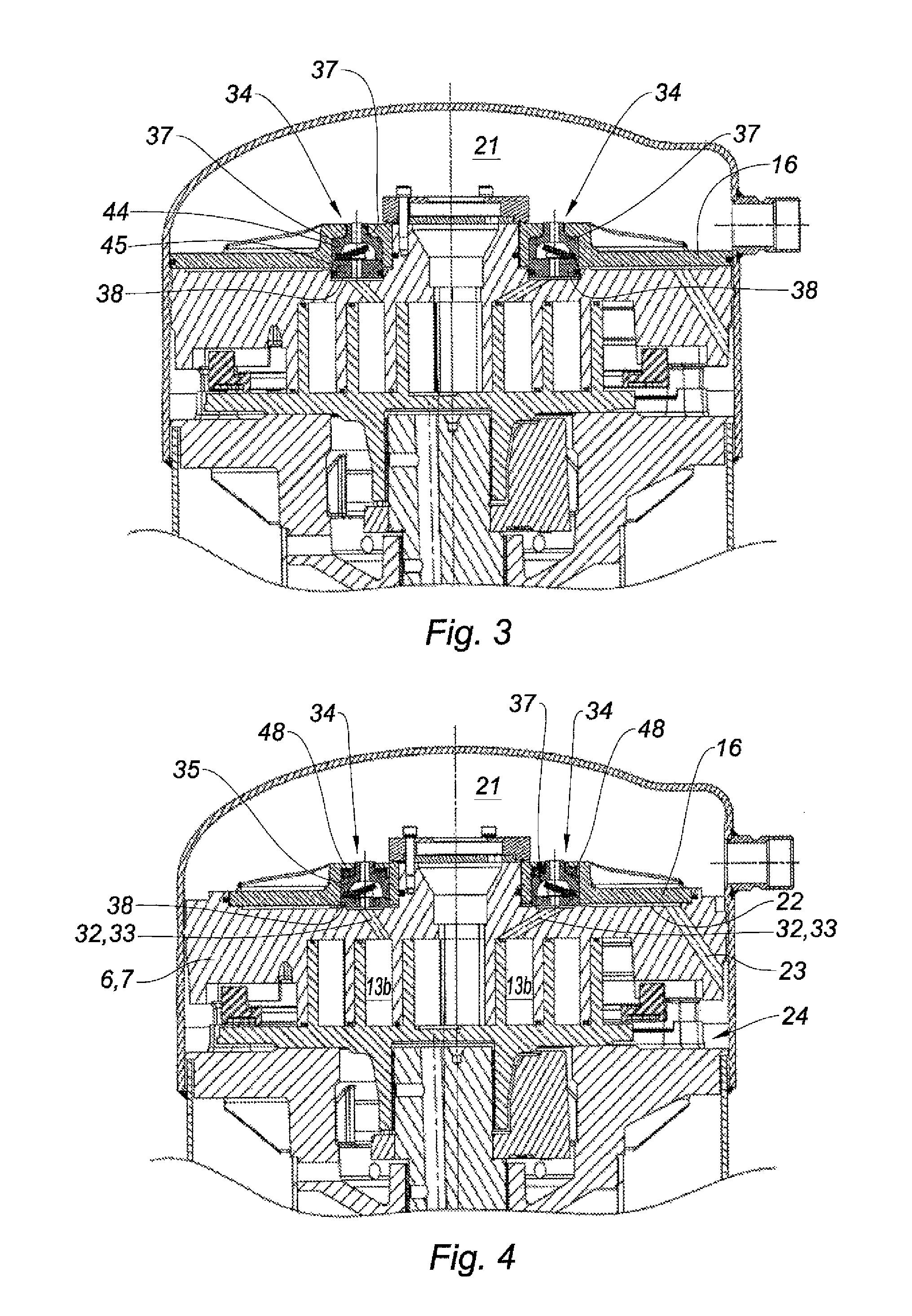
[0088]FIG. 3 shows a compressor according to the invention that differs from that shown in FIG. 1 essentially in that the outer edge of the separating member 16 sealably cooperates with the inner wall of the cover 3, and in that the first portion 37 of the enclosure 35 of each anti-return device 34 is forcibly mounted in the corresponding housing 44 defined by the separating member 16, and the second portion 38 of said enclosure 35 is slidingly mounted parallel to the axis of the compressor in the corresponding housing 45 formed in the plate 7 of the stationary volute 6. In order to ensure sealing between the second portion 38 of each enclosure 35 and the plate 7 of the stationary volute 6, the second portion 38 of each enclosure includes, on the outer surface thereof, an annular groove in which an annular seal is mounted.

third embodiment

[0089]FIG. 4 shows a compressor according to the invention that differs from that shown in FIG. 1 essentially in that the compressor comprises elastic means arranged to bias the enclosure of each anti-return device 34 against the plate 7 of the stationary volute, and in that the second portion 38 of the enclosure 35 of each anti-return device 34 is not mounted in a housing formed in the plate of the stationary volute.

[0090]Preferably, the elastic means include a spiral spring 48 disposed around the second tubular part 37b of the first portion 37 of the enclosure 35 of each anti-return device 34, and respectively bearing against the corresponding bottom wall 44b and the corresponding shoulder 37c.

[0091]According to this embodiment, the enclosure 35 of each anti-return device 34 is movable with respect to the plate 7 of the stationary volute 6 between a first position, in which it sealably bears against the plate 7 of the stationary volute 6, and a second position, in which said encl...

fourth embodiment

[0093]FIG. 5 shows a compressor according to the invention that differs from that shown in FIG. 1 essentially in that the second portion 38 of the enclosure 35 of each anti-return device 34 is also slidingly mounted parallel to the axis of the compressor in the corresponding housing 45 formed in the plate 7 of the stationary volute 6.


PUM


Abstract

The scroll refrigeration compressor includes a stationary volute and a moving volute provided with spiral wraps defining variable-volume compression chambers, a separating member sealably mounted on a plate of the stationary volute so as to allow a relative movement between the separating member and the stationary volute, a delivery chamber at least partially defined by the separating member and the sealed casing. The compressor further includes a bypass passage arranged to communicate the delivery chamber with an intermediate compression chamber, and a anti-return device comprising a closing member movable between closing and opening positions for closing and opening the bypass passage, and an enclosure, positioned between the separating member and the plate of the stationary volute, including a first portion sealably mounted in a housing defined by the separating member and oriented substantially parallel to the longitudinal axis of the compressor.

Description

BACKGROUND[0001]The present invention relates to a scroll refrigeration compressor.[0002]In a known manner, a scroll refrigeration compressor comprises a sealed casing containing a stationary volute and moving volute following an orbital movement, each volute including a plate from which a spiral wrap extends, the spiral wraps of the stationary and moving volutes being engaged in one another and defining variable-volume compression chambers, the compression chambers having a volume that decreases gradually from the outside, where the refrigerant gas is admitted, toward the inside.[0003]Thus, during the relative orbital movement of the first and second volutes, the refrigerant gas is compressed due to the decrease in the volume of the compression chambers and conveyed to the center of the first and second volutes. The compressed refrigerant gas leaves from the central part toward a delivery chamber through a delivery conduit formed in the central part of the first volute.[0004]In ord...

Claims


Application Information

Patent Timeline
Patent Type & Authority Patents(United States)
IPC IPC(8): F01C1/02F03C2/00F04C2/00F04C18/02F04C23/00F04C28/26F04C29/12
CPCF04C18/0207F04C18/0253F04C18/0261F04C28/26F04C29/128F04C18/0215F04C23/008
Inventor GINIES, PIERREBRON, MICKAELGROSS, DOMINIQUEWATTS, STEPHANEMEYNAND, FRANCK
Owner DANFOSS COMML COMPRESSORS
Why Eureka
Try Eureka