Discharge valve arrangement for a hermetic compressor

a technology of hermetic compressor and discharge valve, which is applied in the direction of machines/engines, mechanical equipment, and positive displacement liquid engines, etc., can solve the problems of affecting the capacity and affecting the efficiency of these applications, and rarely using multiple orifices

Inactive Publication Date: 2011-05-05
WHIRPOOL SA +1
View PDF15 Cites 4 Cited by
  • Summary
  • Abstract
  • Description
  • Claims
  • Application Information

AI Technical Summary

Benefits of technology

[0019]For residential applications with low condensation temperature and operating with refrigerant fluid R600a, the invention described herein and provided with multiple discharge orifices present benefits, since the reduction of the load losses in the discharge system compensates for the harmful effect of the dead volume. Moreover, the compressors working with a refrigerant fluid R600a use pistons with larger diameters than those operating with a refrigerant fluid R134a, generating an adequate space for housing the multiple orifices.

Problems solved by technology

Part of the energy losses in these compressors is caused by the load loss in the suction and discharge system thereof.
In residential applications, the constructions with multiple orifices are rarely employed, mainly due to the considerable increase of dead volume, which is more harmful to the capacity and efficiency in these applications.
Such solutions, however, still present the inconveniences of low performance caused by load loss in the discharge system, mainly in applications with low condensation pressures, in applications for refrigeration with low mass flow, and in certain solutions that use refrigerant fluid R600a.

Method used


Image

  • Discharge valve arrangement for a hermetic compressor
  • Discharge valve arrangement for a hermetic compressor
  • Discharge valve arrangement for a hermetic compressor

Examples


Embodiment Construction

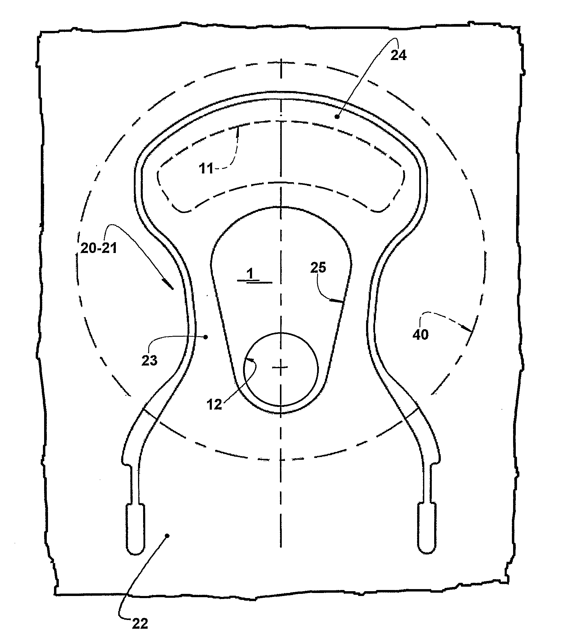
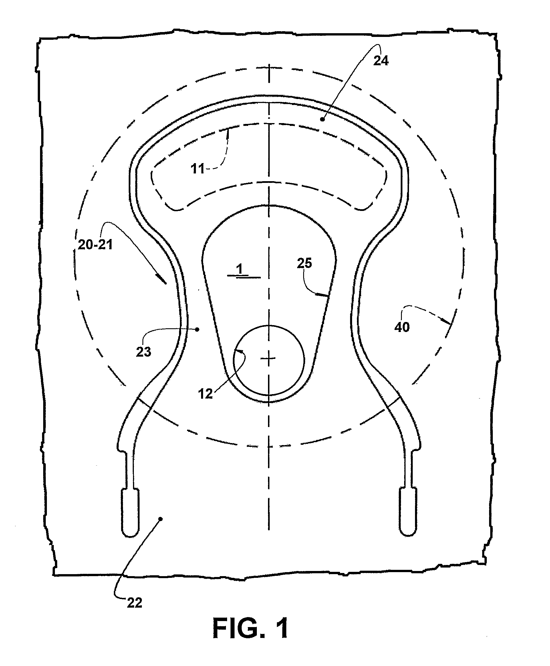
[0031]The present invention will be described for a hermetic compressor of refrigeration systems, to be applied, for example, in household refrigeration systems and comprising, in the interior of a non-illustrated casing, a motor-compressor assembly (not illustrated) including a cylinder block defining a compression cylinder 1 inside which is housed a reciprocating piston 2, which draws and compresses the refrigerant gas when driven by an electric motor of the motor-compressor assembly. In these constructions, the compression cylinder 1 and the reciprocating piston 2 have a reduced diameter, which restricts the space to provide and arrange the suction and discharge valves.

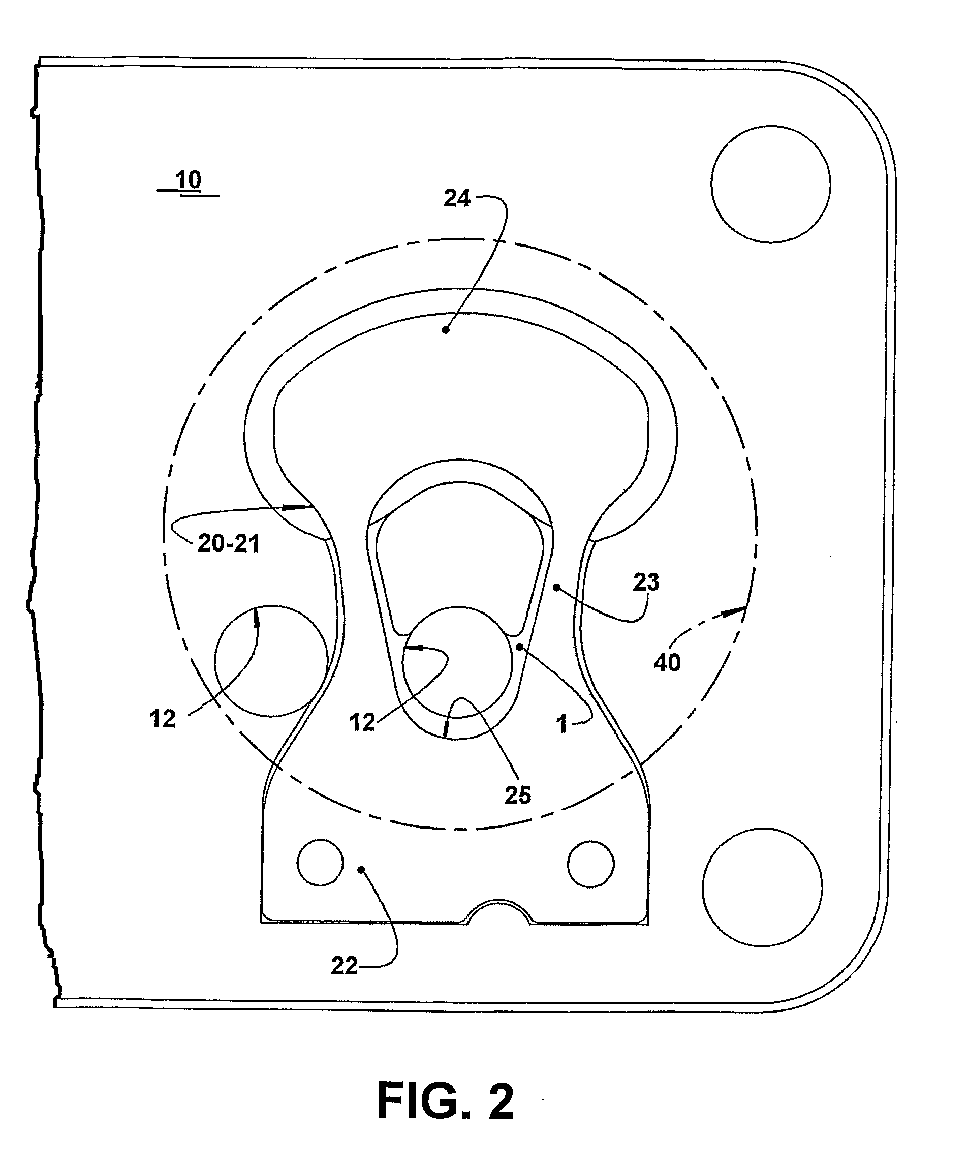
[0032]The compression cylinder 1 has an end closed by a valve plate 10 affixed to the cylinder block and provided with suction orifices 11 and discharge orifices 12. In the interior of the compression cylinder 1, between the top of the reciprocating piston 2 and the valve plate 10, it is defined a compression chamb...


PUM


Abstract

Discharge valve arrangement applied in a hermetic compressor used, for example, in household refrigeration systems including a valve plate closing an end of a compression cylinder and provided with suction and discharge orifices contained within the inner contour of the axial projection of the compression cylinder, said suction orifice occupying an annular sector external to the axial projection of a discharge orifice and being closed by a flexible suction vane having a bending median portion. The valve plate is provided with a plurality of discharge orifices distributed in at least one of the regions defined externally and internally to the contour of the flexible suction vane, each discharge orifice provided internally to the contour of the flexible suction vane being axially aligned with a respective through opening provided in said bending median portion.

Description

FIELD OF THE INVENTION[0001]The present invention refers to a discharge valve arrangement for a hermetic compressor to be used in refrigeration systems, for example, in household refrigeration systems, such as refrigerators, freezers, water fountains, etc., or even in electronic equipment using compact compressors with reduced dimensions.[0002]The present invention is particularly applied to a hermetic compressor comprising a cylinder block defining a compression cylinder with an end closed by a valve plate provided with suction and discharge orifices contained within the inner contour of the axial projection of the compression cylinder. At least one suction orifice occupies an annular sector and is closed by a suction valve comprising a flexible suction vane that presents a mounting end portion, to be affixed to the valve plate, a bending median portion and a sealing end portion that is operatively associated with the suction orifice.BACKGROUND OF THE INVENTION[0003]The energetic e...

Claims


Application Information

Patent Timeline
Patent Type & Authority Applications(United States)
IPC IPC(8): F04D25/10
CPCF04B39/1073
Inventor RIBAS JUNIOR, FERNANDO ANTONIOMOREIRA, EMERSONDESCHAMPS, CESAR JOSEPEREIRA, EVANDRO LUIZ LANGE
Owner WHIRPOOL SA
Why Eureka
Try Eureka