Fluid-cooling device for a turbine engine propulsive unit

a turbine engine and propulsive unit technology, applied in liquid fuel engines, machines/engines, light and heating apparatus, etc., can solve the problems of reducing the efficiency of propellers

Active Publication Date: 2015-11-03
AIRBUS OPERATIONS (SAS) +1
View PDF11 Cites 8 Cited by
  • Summary
  • Abstract
  • Description
  • Claims
  • Application Information

AI Technical Summary

Benefits of technology

[0035]The goal here is to make it possible to control the cooler betwee

Problems solved by technology

Although it has very high efficiency, this gearbox dissipates part of the energy created by the propulsion unit into heat by friction.
Moreover, the turbomachine itself generates significant heat dissipation mainly by mechanical friction, also through its lubricant.
The major drawbacks of this solution are:Significant impact on the e

Method used


Image

  • Fluid-cooling device for a turbine engine propulsive unit
  • Fluid-cooling device for a turbine engine propulsive unit
  • Fluid-cooling device for a turbine engine propulsive unit

Examples


Embodiment Construction

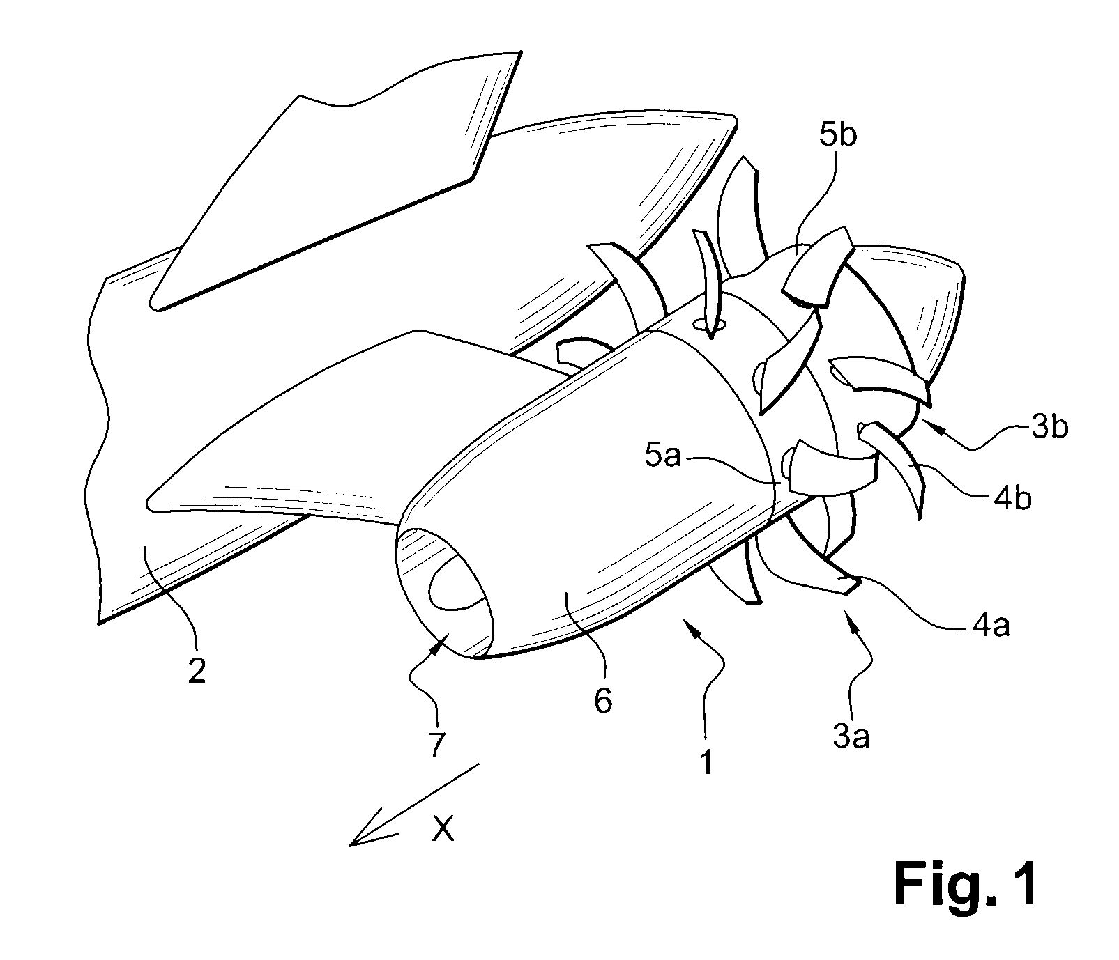
[0048]The invention is intended to be used in an airplane propulsion unit 1, for example of the type called “propfan”, as shown in FIG. 1. Such engines are envisaged for future aircraft. In the example of implementation illustrated here, two propfan propulsion units 1 are attached by engine pylons, on both sides of the rear part of an aircraft fuselage 2.

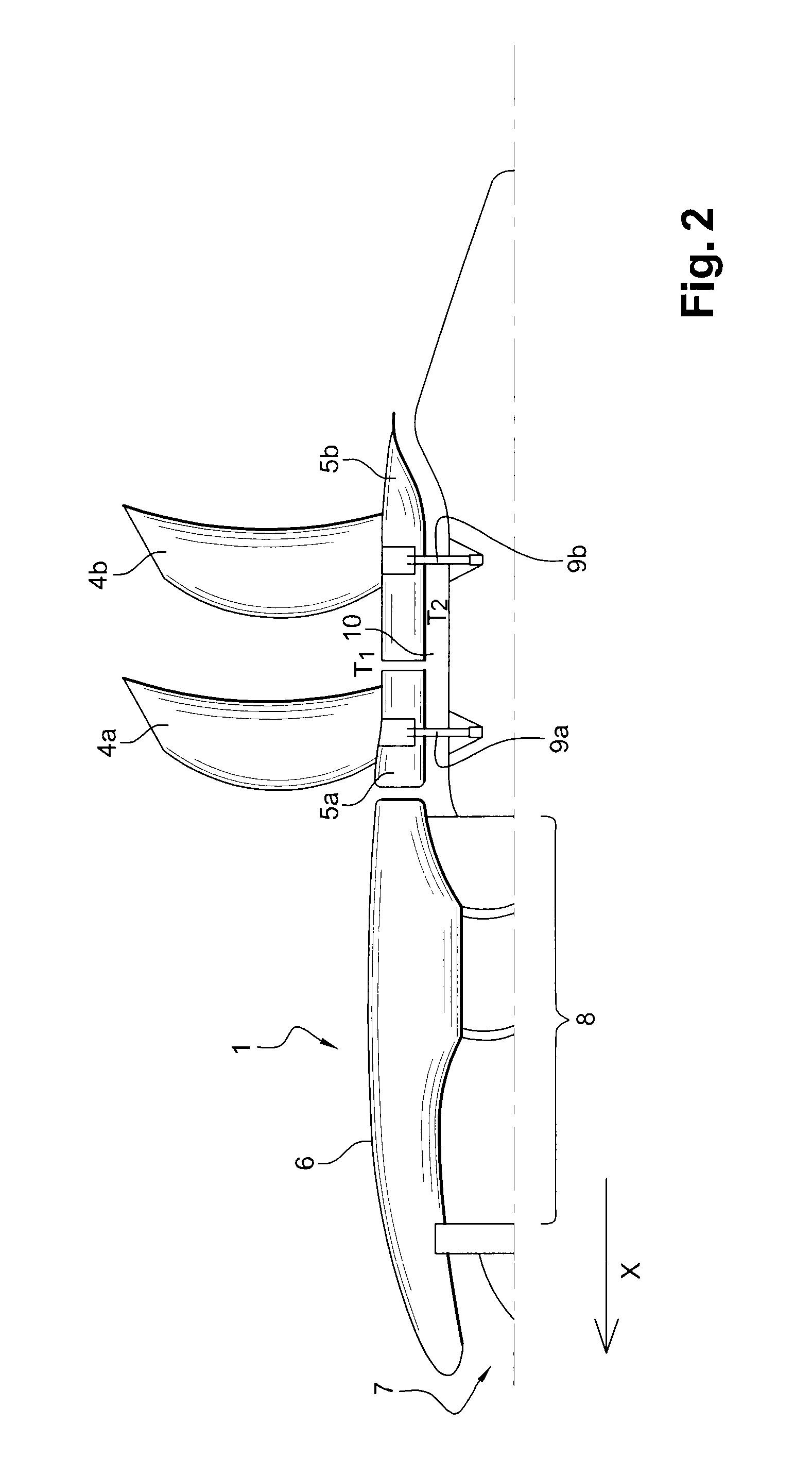
[0049]Each propfan propulsion unit 1 here comprises two counter-rotating rotors 3a, 3b each comprising a set of equidistant blades 4a, 4b and positioned in the rear part of the propulsion unit 1. The blades 4a, 4b of each rotor 3a, 3b protrude from an annular crown 5a, 5b, which is mobile with this rotor, the outer surface of which is located in the continuity of the outer envelope 6 of the propulsion unit.

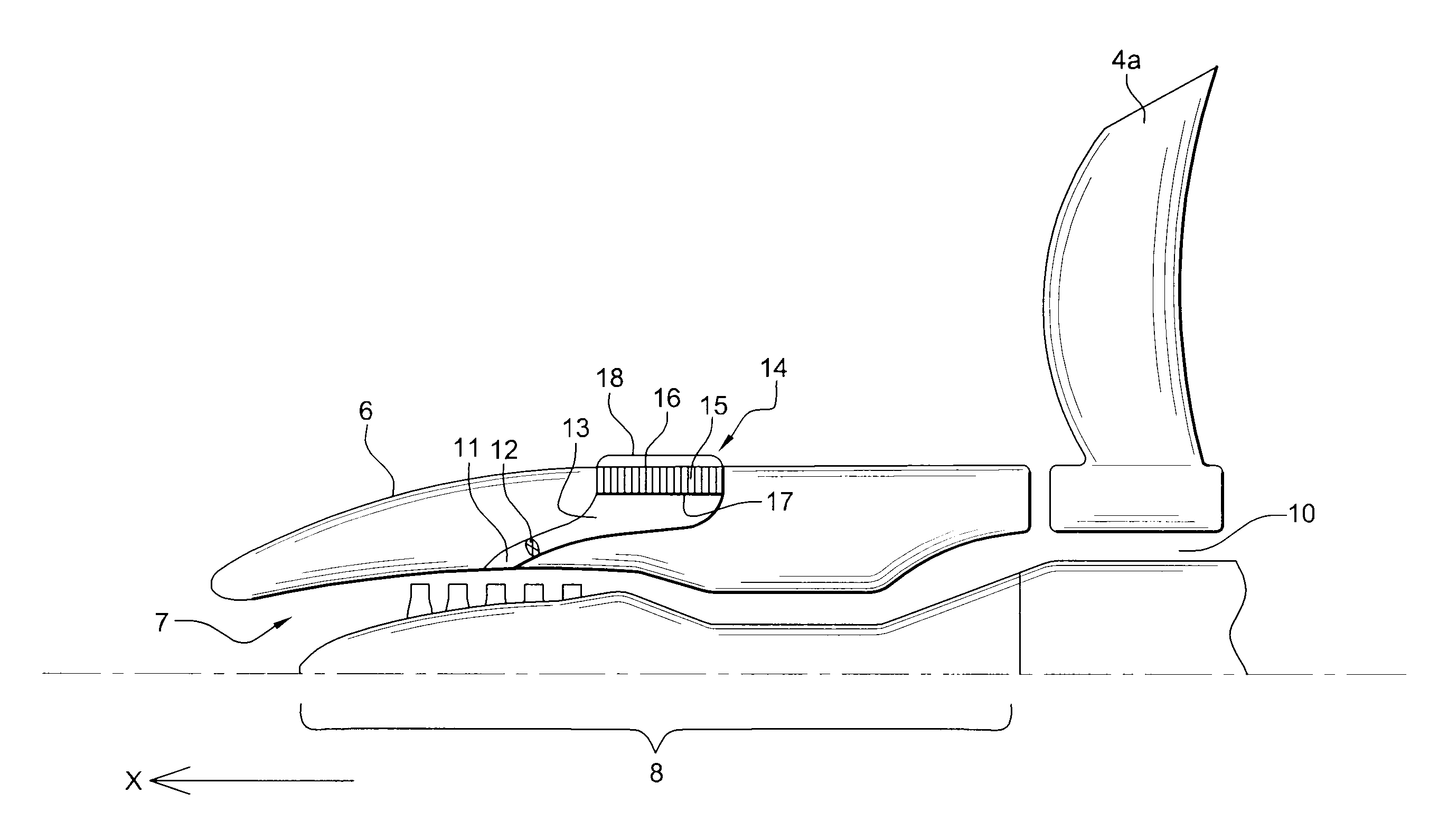
[0050]As shown schematically in FIG. 2 the propfan propulsion unit 1 comprises an air inlet 7 that supplies a turbomachine 8. This turbomachine 8 comprises an axial portion driven in rotation when the turbomachine is running. In t...


PUM


Abstract

A fluid cooling device for the propulsion unit of a propfan type aircraft including a compressed air intake at the air compressor of the turbomachine, an air vein capable of conveying the collected compressed air to a cooler, and a system for conveying the heat of the lubricant to the cooler is provided. The cooler includes a matrix body provided with a plurality of ducts for a cooling agent, the ducts extending along a first inner surface up to a second outer surface of the matrix body such that the collected pressurized air serving as a cooling agent can pass through the matrix body, the matrix body of the cooler forming a portion of the outer skin of the propulsion unit; and a set of fins extending from the outer surface towards the outside of the propulsion unit, and oriented mainly parallel to the air flow direction when the aircraft is in flight.

Description

BACKGROUND OF THE INVENTION[0001]1. Field of the Invention[0002]The present invention relates to the field of aeronautical equipment. It relates more specifically to heat dissipation systems, and even more particularly heat sinks for turbomachine-type aircraft propulsion units.[0003]2. Description of the Related Art[0004]A large number of aircraft propulsion units comprise a turbomachine; this is the case, for example, for propfan-type aircraft propulsion units, where this turbomachine drives two counter-rotating rotors.[0005]In these propulsion units, a gearbox (gears between the turbomachine axle and the rotors) transmits the mechanical energy generated by the turbomachine to the rotors.[0006]Although it has very high efficiency, this gearbox dissipates part of the energy created by the propulsion unit into heat by friction. This heat is transmitted in particular to the gearbox lubricant.[0007]Moreover, the turbomachine itself generates significant heat dissipation mainly by mecha...

Claims


Application Information

Patent Timeline
IPC IPC(8): F01D25/12F02C6/08B64D33/10B64D29/00F04D29/58F02C7/14F28F27/02F28F13/00F02K1/46F02K3/072F28D1/03F28D1/04F28F1/32F28F1/34B64D33/02B64D27/02F28D21/00
CPCF04D29/584B64D29/00B64D33/10F02C6/08F02C7/14F02K1/46F02K3/072F28D1/03F28D1/04F28F1/32F28F1/34F28F13/00F28F27/02B64D2027/026B64D2033/0286B64D2241/00F05D2220/325F28D2021/0078Y02T50/67Y02T50/672Y02T50/675F28F2265/00Y02T50/60
Inventor BULIN, GUILLAUMESTOLTE, RALF-HENNING
Owner AIRBUS OPERATIONS (SAS)
Why Eureka
Try Eureka