
Valve assembly for variable swash plate compressor

Active Publication Date: 2015-03-26
HANON SYST
View PDF6 Cites 4 Cited by
  • Summary
  • Abstract
  • Description
  • Claims
  • Application Information

AI Technical Summary

Benefits of technology

The present invention presents a valve assembly for a variable swash plate compressor that can improve performance without speeding up the motor. It does this by changing the shape of the valve components to increase the flow rate. Additionally, the valve assembly can prevent damage to the piston by extending its service life.

Problems solved by technology

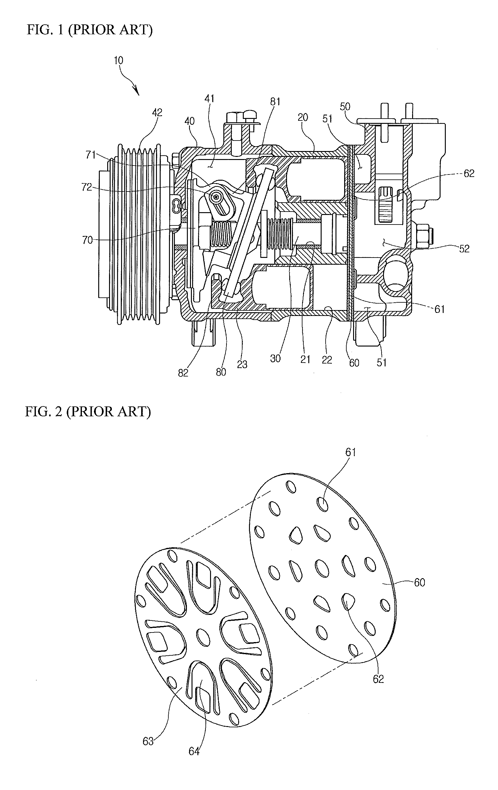
However, when the compressor is merely driven at high speed for increasing a flow rate of refrigerant, there are problems in that noise and pulsation are increased and durability of the compressor is deteriorated.
Consequently, since the refrigerant is not normally compressed and discharged, the compressor 10 may not be operated.

Method used


Image

  • Valve assembly for variable swash plate compressor
  • Valve assembly for variable swash plate compressor
  • Valve assembly for variable swash plate compressor

Examples


Embodiment Construction

[0065]Exemplary embodiments of the present invention will be described below in more detail with reference to the accompanying drawings. The present invention may, however, be embodied in different forms and should not be construed as limited to the embodiments set forth herein. Rather, these embodiments are provided so that this disclosure will be thorough and complete, and will fully convey the scope of the present invention to those skilled in the art. Therefore, it should be understood that the scope and spirit of the present invention can be extended to all variations, equivalents, and replacements in addition to the appended drawings of the present invention. In the description, the thickness of each line or the size of each component illustrated in the drawings may be exaggerated for convenience of description and clarity.

[0066]In addition, terms to be described later are terms defined in consideration of functions of the present invention, and these may vary with the intenti...


PUM


Abstract

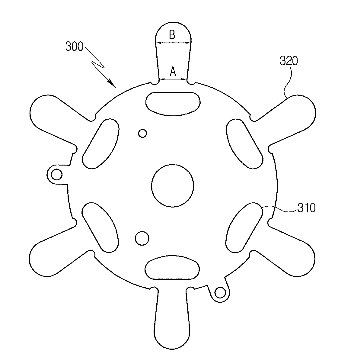
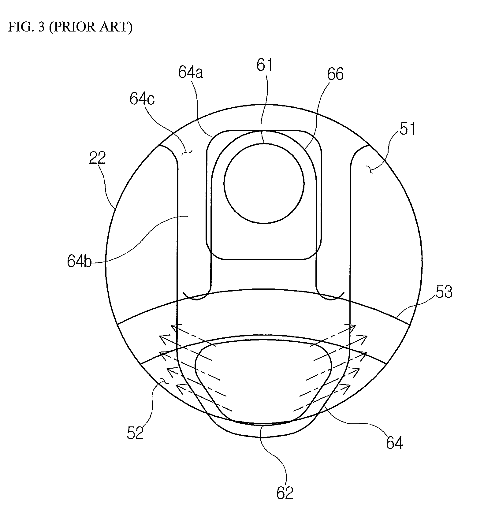
Disclosed herein is a valve assembly for a variable swash plate compressor. Since an opening hole of a suction reed is enlarged toward a suction port of a valve plate and refrigerant is also introduced into a cylinder bore through the opening hole when the suction port is opened, performance of a compressor may be enhanced by an increase in flow rate.

Description

CROSS-REFERENCE TO RELATED APPLICATIONS[0001]This application claims priority to Korean Patent Application Nos. 10-2014-0027085, 10-2014-0032247, and 10-2013-0112369, filed on Mar. 7, 2014, Mar. 19, 2014, and Sep. 23, 2013, respectively, the disclosures of which are incorporated herein by reference in their entirety.FIELD OF THE INVENTION[0002]Exemplary embodiments of the present invention relate to a valve assembly for a variable swash plate compressor, and more particularly, to a valve assembly for a variable swash plate compressor, capable of enhancing performance of a compressor through an increase in flow rate and extending a life of the compressor through an improvement of durability thereof.BACKGROUND OF THE INVENTION[0003]In general, compressors serving to compress refrigerant in vehicle cooling systems have been developed in various forms. The compressors are basically classified into a reciprocating compressor which performs compression by reciprocating motion and a rotary...

Claims


Application Information

Patent Timeline
IPC IPC(8): F04B1/20
CPCF04B1/2078F04B1/2042F04B39/1066F04B39/1073F04B27/10F04B27/1009F04B27/08
Inventor BAE, SANG WOOSON, EUN GIYUN, JE SUSONG, SE YOUNGYOON, YOUNG SEOPLEE, SUNG MYUNGAHN, HEW NAMLIM, SEUNG TAEK
Owner HANON SYST
Learn More