Utilization of bypass refrigerant to provide reheat and dehumidification function in refrigerant system

Inactive Publication Date: 2006-04-13
CARRIER CORP
View PDF5 Cites 5 Cited by
  • Summary
  • Abstract
  • Description
  • Claims
  • Application Information

AI Technical Summary

Benefits of technology

[0009] The present invention utilizes the bypass of the compressed refrigerant that is passing from the compressor back to the compressor suction as a source of heat for this reheat function. In this way, a dedicated re

Problems solved by technology

These opposite trends have presented challenges to refrigerant system designers.
Known reheat systems require additional components such as flow control devices, and are susceptible to refrigerant charge migration problems that may affect system operational characteristics, functionality and reliability over a wide range of environmental and operating conditions.
At the same time, the temperature of the combined refrigera

Method used


Image

  • Utilization of bypass refrigerant to provide reheat and dehumidification function in refrigerant system
  • Utilization of bypass refrigerant to provide reheat and dehumidification function in refrigerant system

Examples


Embodiment Construction

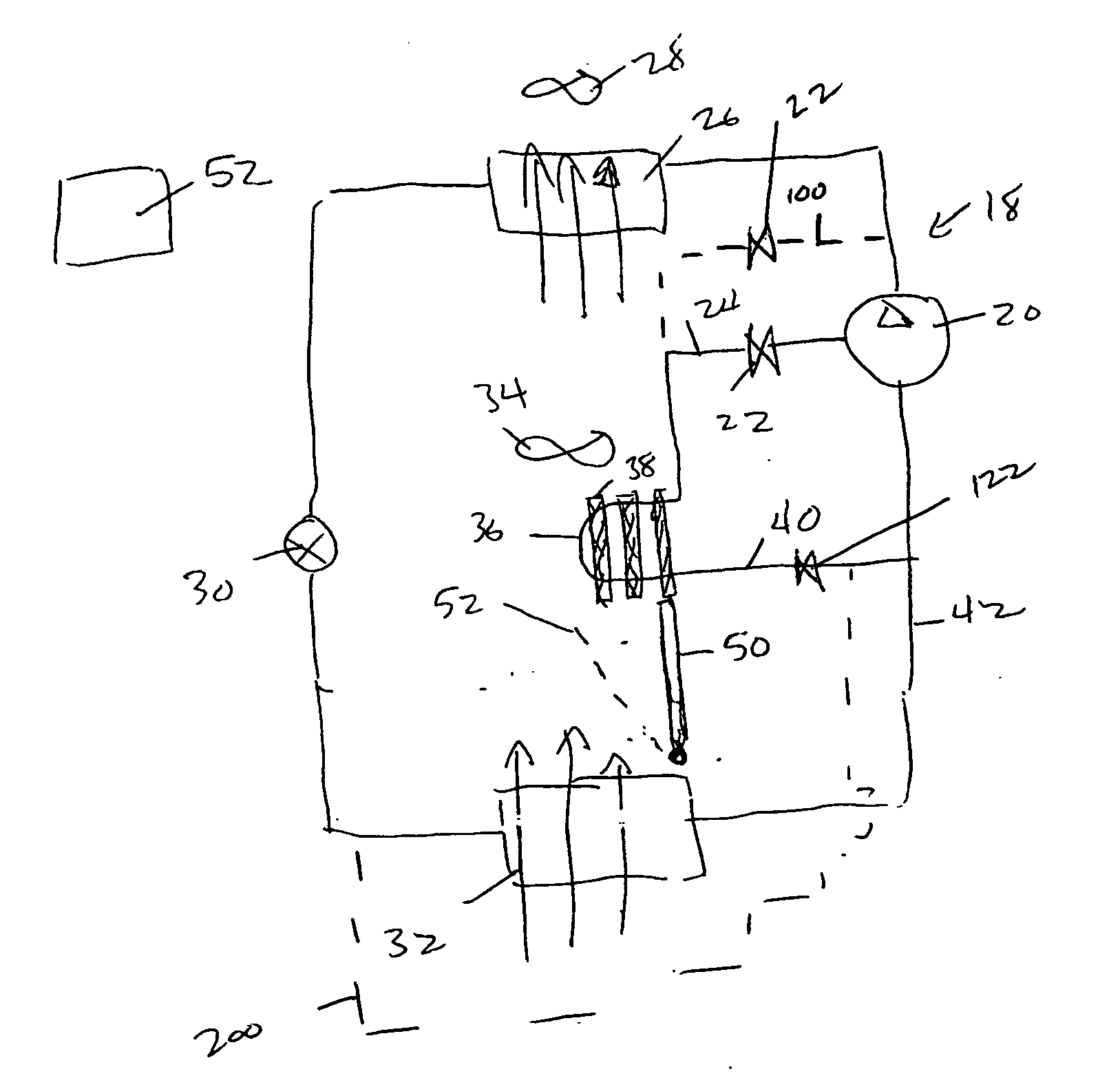
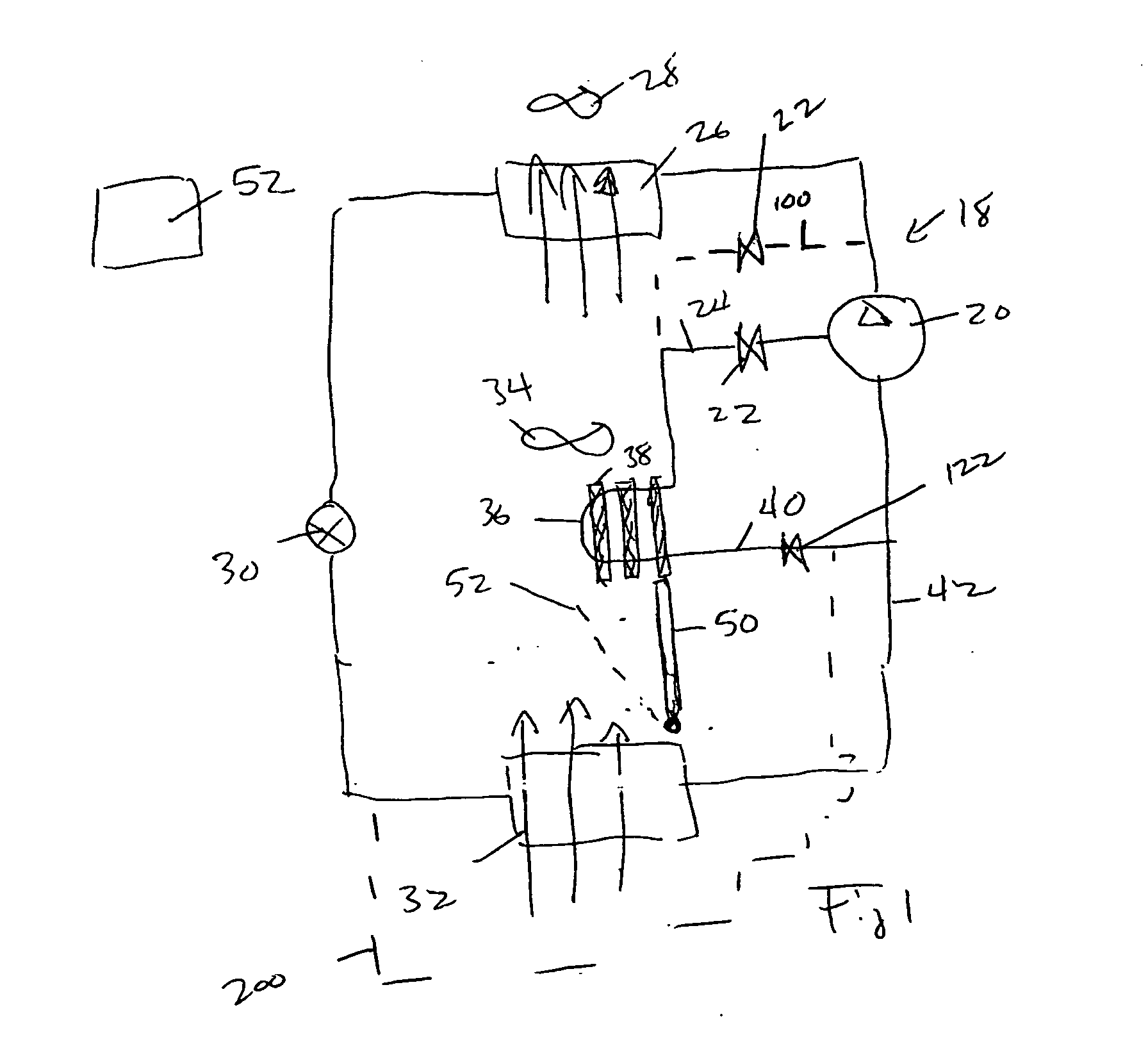
[0013] A refrigerant cycle 18 includes a compressor 20 having a valve 22 for selectively bypassing a portion of compressed refrigerant into a bypass line 24 and then back to the compressor suction. The main flow of refrigerant that has been compressed by the compressor 20 moves downstream to a condenser 26. An air-moving device 28 moves air over the condenser 26 providing heat transfer interaction (heat rejection) between the refrigerant and air. Downstream of the condenser 26, the refrigerant enters an expansion device 30, and then an evaporator 32. An air-moving device 34 moves air over the evaporator 32 to be cooled and dehumidified, as known. The bypass line 24 has a section 36 placed in the path of this air stream flowing over the evaporator 32. As shown, extended heat transfer structure such as fins 38 may be added to the section 36 to increase its heat transfer capability. As generally known, when a desired dehumidification level is to be achieved, that would result in the ai...


PUM


Abstract

A refrigerant system is provided with an unloader bypass line to selectively unload the compressor and deliver refrigerant from a partially (or fully) compressed location back to a suction port of the compressor. A section of this unloader bypass line is placed in the path of air having passed over an evaporator and towards an environment to be conditioned. This section of the unloader bypass line would contain refrigerant that is at a higher temperature than the refrigerant, which had been delivered into the evaporator by the main circuit. In this manner, this bypass line section will provide the function of reheating the air above the temperature to which it had been cooled in the evaporator to achieve a desired humidity level. Thus, the reheat function is obtained without requiring a dedicated reheat loop, associated components and additional structure. Also, through the refrigerant temperature reduction, compressor reliability and performance are improved. Furthermore, the flow control device may be of an adjustable type (e.g. modulating or pulsating) to achieve variable sensible heat ratios and to cover a wide range of potential applications. Lastly, the bypass line may have extended heat transfer elements allowing heat transfer enhancement between the air and refrigerant.

Description

BACKGROUND OF THE INVENTION [0001] This application relates to a refrigerant system having a reheat function provided by hot refrigerant in a bypass line. [0002] Refrigerant systems are utilized in applications to change the temperature and humidity or otherwise condition the environment. In a standard refrigerant system, a compressor delivers a compressed refrigerant to a heat exchanger, known as a condenser, which is typically located outside. From the condenser, the refrigerant passes through an expansion device, and then to an indoor heat exchanger, known as an evaporator. At the evaporator, moisture may be removed from the air, and the temperature of air blown over the evaporator coil is lowered. From the evaporator, the refrigerant returns to the compressor. Of course, basic refrigerant cycles are utilized in combination with many configuration variations and optional features. However, the above provides a brief understanding of the fundamental concept. [0003] In some cases, ...

Claims


Application Information

Patent Timeline
IPC IPC(8): F25B41/00F25B49/00
CPCF24F3/153F25B2600/0261
Inventor LIFSON, ALEXANDERTARAS, MICHAEL F.
Owner CARRIER CORP
Why Eureka
Try Eureka