Thermoelectric energy storage system and an associated method thereof

a technology of energy storage system and thermal energy, which is applied in the direction of indirect heat exchangers, machines/engines, lighting and heating apparatus, etc., can solve the problems of limited deployment, limited thermodynamic cycle performance in charge cycle and discharge cycle, and significant temperature between working fluid and thermal sour

Active Publication Date: 2018-11-29
GENERAL ELECTRIC CO
View PDF4 Cites 31 Cited by
  • Summary
  • Abstract
  • Description
  • Claims
  • Application Information

AI Technical Summary

Benefits of technology

[0005]Thus, there is a need for an improved e

Problems solved by technology

However, such energy storage systems may require access to underground caverns for retaining pressure of the compressed fluid, which may not be economical and thus may be of limited deployment.
However, performance of thermodynamic cycles in the charge cycle and discharge cycle are limited by temperature constraints and available thermal sources.
Typically, the difference in the temperature between the working fluid and the therm

Method used


Image

  • Thermoelectric energy storage system and an associated method thereof
  • Thermoelectric energy storage system and an associated method thereof
  • Thermoelectric energy storage system and an associated method thereof

Examples


Embodiment Construction

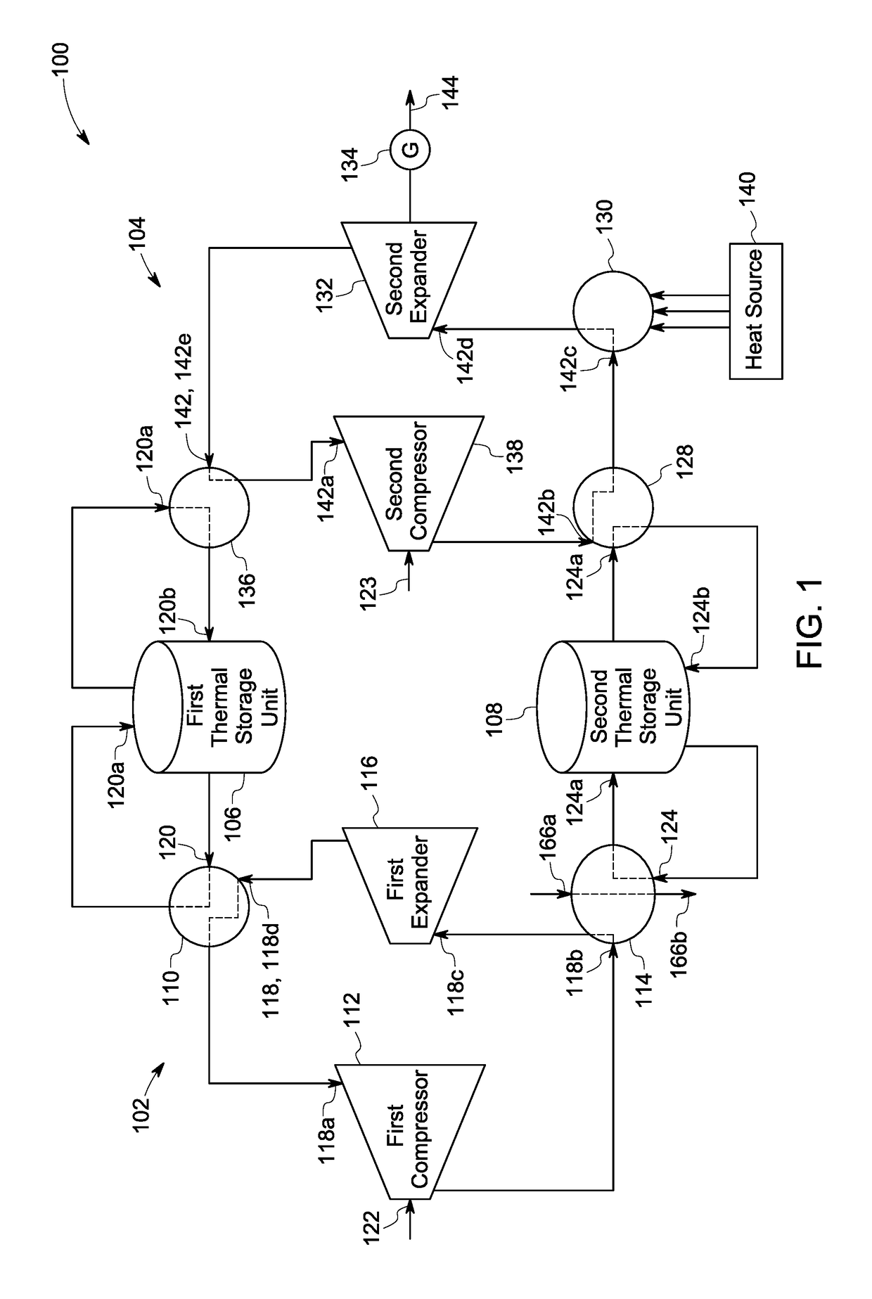
[0017]Embodiments discussed herein disclose a thermoelectric energy storage system including a refrigeration system, a power system, a first thermal storage unit, and a second thermal storage unit. In certain embodiments, the thermoelectric energy storage system is configured to efficiently store a portion of thermal energy in the second thermal storage unit (hereinafter also referred to as an “intermediate thermal storage unit”) while operating the refrigeration system. Further, the thermoelectric energy storage system is configured to retrieve the portion of the thermal energy from the intermediate thermal storage unit while operating the power system. In certain embodiments, the refrigeration and power systems are operated in a time-shift arrangement. In other words, the refrigeration and power systems are operated alternately. For example, the refrigeration system may be operated during night, when a demand for electric power is lower, and the power system may be operated during...


PUM


Abstract

Thermoelectric energy storage system and an associated method are disclosed. The thermoelectric energy storage system includes a first refrigeration system, a power system, a first thermal storage unit, and a second thermal storage unit. The first refrigeration system includes a first heat exchanger, a first compressor, a second heat exchanger, and a first expander. The first heat exchanger is disposed upstream relative to the first compressor. The power system includes a third heat exchanger, a second compressor, a fourth heat exchanger, a fifth heat exchanger, and a second expander. The third heat exchanger is disposed upstream relative to the fourth heat exchanger. The fifth heat exchanger is disposed downstream relative to the second expander. The first thermal storage unit is coupled to the first heat exchanger and the fifth heat exchanger. The second thermal storage unit is coupled to the first refrigeration system and the power system.

Description

[0001]This disclosure was made with Government support under contract number DE-AR0000467 awarded by U.S. Department of Energy. The Government has certain rights in the disclosure.BACKGROUND[0002]Embodiments of the present invention relate generally to energy storage systems and more particularly to a thermoelectric energy storage system and an associated method thereof.[0003]Energy storage systems, such as electrical energy storage systems may use a charge cycle for storing energy and a discharge cycle for retrieval of the stored energy. In a thermoelectric energy storage system, during the charge cycle, a compressor is driven using electric power to compress a fluid and store the energy in a compressed fluid. Further, during the discharge cycle, the compressed fluid is expanded using a turbo expander to drive a generator for retrieval of the stored energy. However, such energy storage systems may require access to underground caverns for retaining pressure of the compressed fluid,...

Claims


Application Information

Patent Timeline
IPC IPC(8): F25B9/06F25B9/00F25B25/00
CPCF25B9/06F25B9/008F25B2400/06F25B2400/141F25B2400/14F25B25/005F01K3/12F01K27/00F25B11/02F25B2339/047F25B2400/24F28D20/02F28D2020/0082Y02E60/14
Inventor PETER, ANDREW MAXWELLHOFER, DOUGLAS CARLSHISLER, ROGER ALLENKALRA, CHIRANJEEVMANN, ANDREW PAUL
Owner GENERAL ELECTRIC CO
Why Eureka
Try Eureka