Liquid Dispensing Nozzle And Device Comprising A Cap
a liquid dispensing nozzle and liquid technology, applied in the field of liquid dispensing nozzles, can solve the problems of not being able to unscrew and not being able to turn, and achieve the effects of improving air circulation, reducing noise, and improving evaporation of residual liquid products
- Summary
- Abstract
- Description
- Claims
- Application Information
AI Technical Summary
Benefits of technology
Problems solved by technology
Method used
Image
Examples
first embodiment
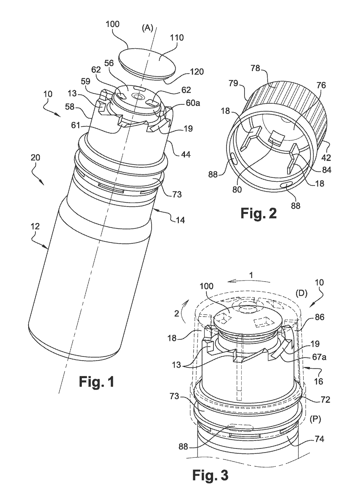
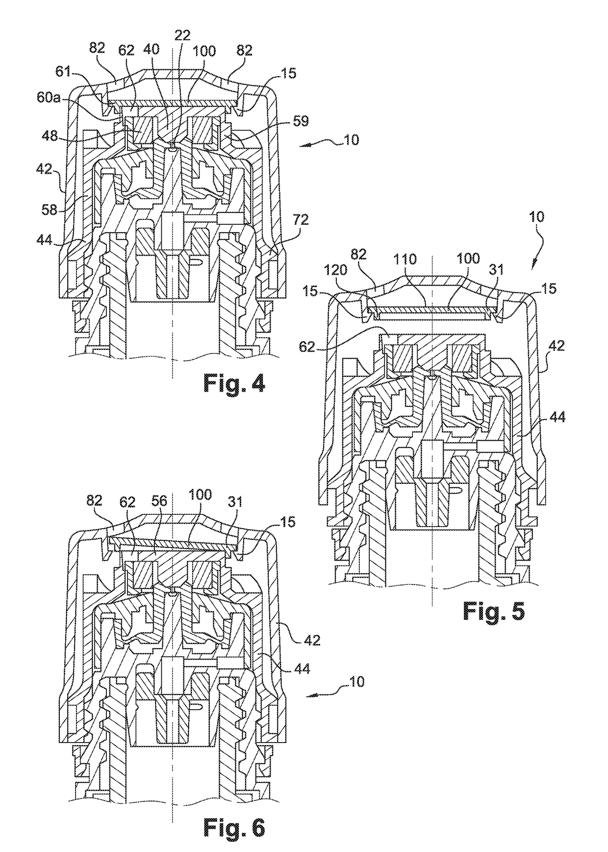
[0051]FIGS. 1 to 6 illustrate the nozzle 10 in which the interior envelope 44 comprises a ceiling 56, a first skirt 58 and a second skirt 59, both of substantially cylindrical shape, interconnected by a plate 61 (see FIG. 1). The ceiling 56 is delimited in this example by a cylindrical surface 60a connecting it to the second skirt 59 and comprises air passage orifices 62, three of them in this example. The cylindrical surface 60a defines a sealing surface. The interior envelope 44 further comprises a peripheral circular groove 73 arranged at the proximal end (P) of the interior envelope 44. The interior envelope 44 further comprises a plurality of guide slopes 67a (see FIG. 3) spaced from one another and extending from the first skirt 58 in the axial direction (A), each guide slope 67a having a sliding surface 19 and a screwing abutment 13. The interior envelope 44 further comprises a frangible ring 74 at the proximal end (P) of the cap 16, as can be seen in FIG. 3.
[0052]As shown in...
second embodiment
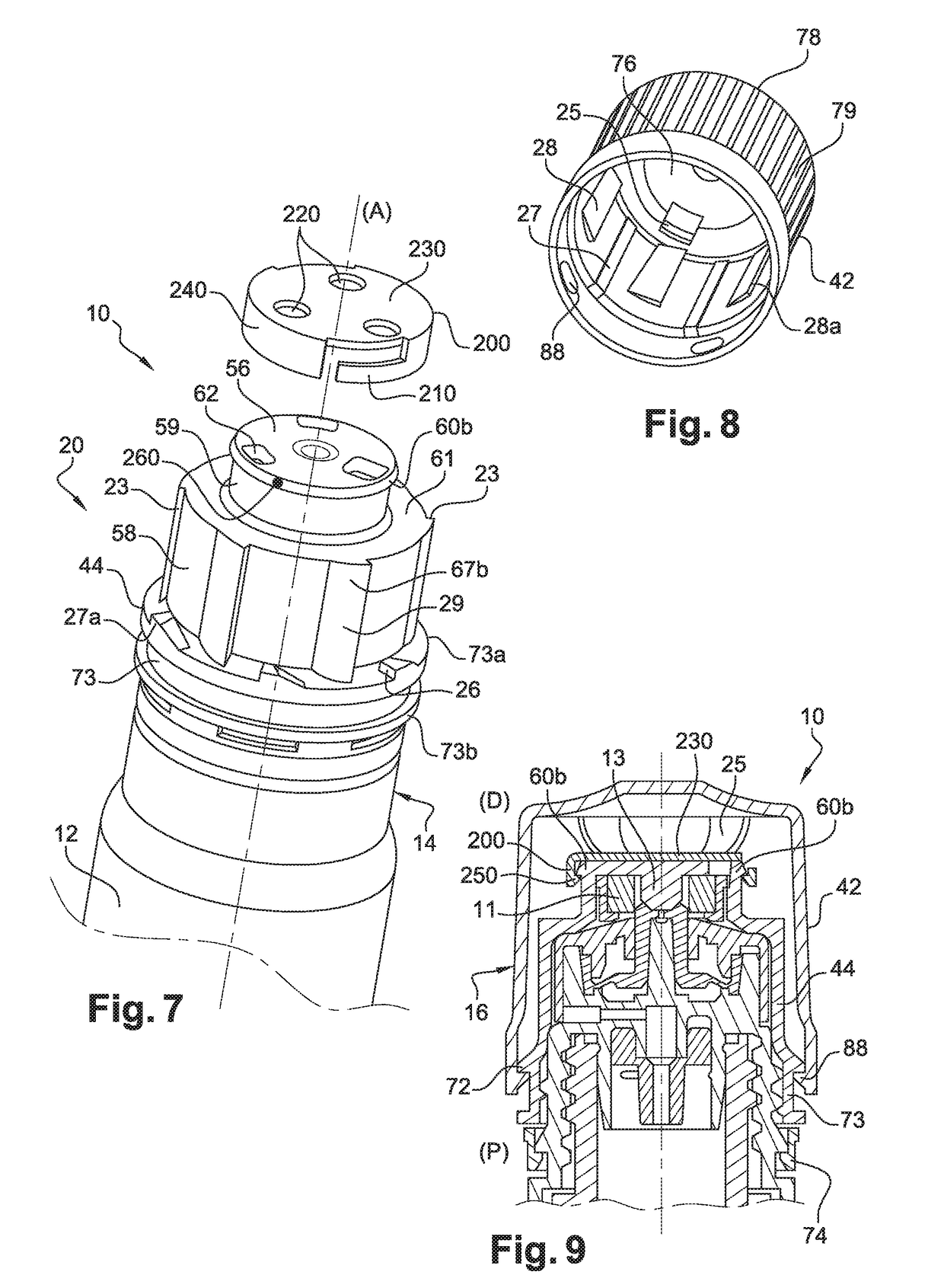
[0064]FIGS. 7 to 11 illustrate the nozzle 10 in which the interior envelope 44 comprises a ceiling 56, a first skirt 58 and a second skirt 59 both of substantially cylindrical shape interconnected by a plate 61. The ceiling 56 comprises air passage orifices 62, three of them in this example. The second skirt 59 comprises at its end a flange 60b having a substantially frustoconical peripheral surface in which are arranged two stopping points 260 on respective opposite sides of the axis of the nozzle 10. In this example the ceiling 56 defines a sealing surface. The interior envelope 44 further comprises a plurality of guide slopes 67b spaced from one another and extending from the first skirt 58 in a transverse direction relative to the axial direction (A), each guide slope 67b including a sliding surface 29 and a screwing abutment 23. The interior envelope 44 further comprises a frangible ring 74 at the proximal end (P) of the cap 16, as can be seen in FIG. 9.
[0065]As in the first em...
third embodiment
[0081]FIGS. 12 to 17 illustrate the nozzle 10 in which the interior envelope 44 comprises a ceiling 56, a first skirt 58 and a second skirt 59 both of cylindrical shape interconnected by a plate 61. As can seen in FIG. 12, the ceiling 56 comprises air passage orifices 62, three of them in this example. The second skirt 59 comprises return means in the form of a deformable wall 60c (see FIG. 15) extending from the periphery of the ceiling 56 and comprises an interior rim at its distal end (D). In this example the rim defines a sealing surface. The interior envelope 44 further comprises a plurality of guide slopes 67c spaced from one another and extending from the first skirt 58 in a transverse direction relative to the axial direction (A), each guide slope 67c including a sliding surface 39 and a screwing abutment 33 (see FIG. 12). The interior envelope 44 further comprises a frangible ring 74 at the proximal end (P) of the cap 16, as can be seen in FIG. 14.
[0082]The interior envelop...
PUM
 Abstract
Description
Claims
Application Information
 - R&D
- Intellectual Property
- Life Sciences
- Materials
- Tech Scout
- Unparalleled Data Quality
- Higher Quality Content
- 60% Fewer Hallucinations
Browse by: Latest US Patents, China's latest patents, Technical Efficacy Thesaurus, Application Domain, Technology Topic, Popular Technical Reports.
© 2025 PatSnap. All rights reserved.Legal|Privacy policy|Modern Slavery Act Transparency Statement|Sitemap|About US| Contact US: help@patsnap.com


