Eureka AIR delivers breakthrough ideas for toughest innovation challenges, trusted by R&D personnel around the world.

Virtual reality display apparatus

a virtual reality and display device technology, applied in the field of display devices, can solve the problems of affecting stray light, and users no longer satisfied with watching two-dimensional images, so as to improve the quality of the images that the user sees, improve the problem of stray light, and reduce the brightness of stray light

Active Publication Date: 2018-12-06
ACER INC
View PDF1 Cites 5 Cited by
  • Summary
  • Abstract
  • Description
  • Claims
  • Application Information

AI Technical Summary

Benefits of technology

The invention is about a virtual reality display that reduces stray light, which can make images appear brighter but without additional information. This is done by using a Fresnel lens with a small radius of curvature to refract image beams in a way that reduces stray light. Additionally, by using an optical micro-structure on the surface of the Fresnel lens, the stray light is scattered and reduced in brightness. This results in a better user experience and higher quality images. Overall, this virtual reality display improves stray light issues to create a better virtual reality experience for users.

Problems solved by technology

As the display technology advances, in pursuit of close-to-reality experiences, users are no longer satisfied with watching two-dimensional images.
However, some surfaces of the optical component may cause part of the light from the display to travel without following the expected direction and path but to be reflected to an unexpected direction and result in stray light.
The stray light affects the quality of the images that the user sees and lessens the visual experience of the user.

Method used


Image

  • Virtual reality display apparatus
  • Virtual reality display apparatus
  • Virtual reality display apparatus

Examples


Embodiment Construction

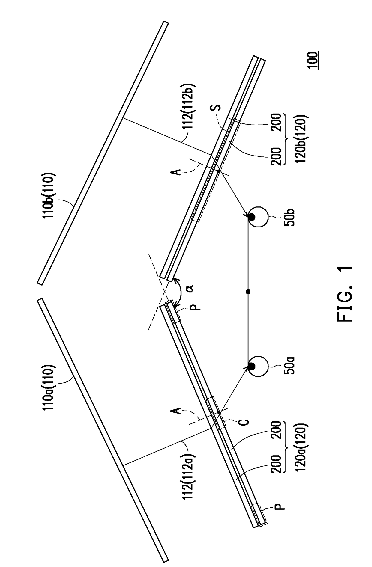
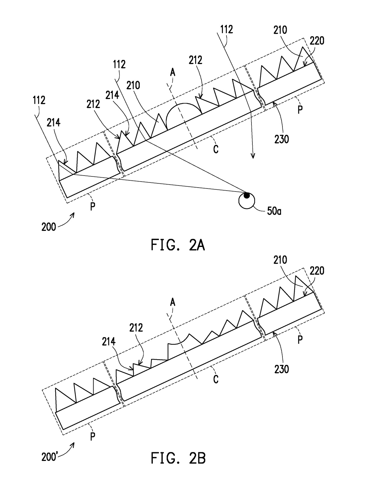
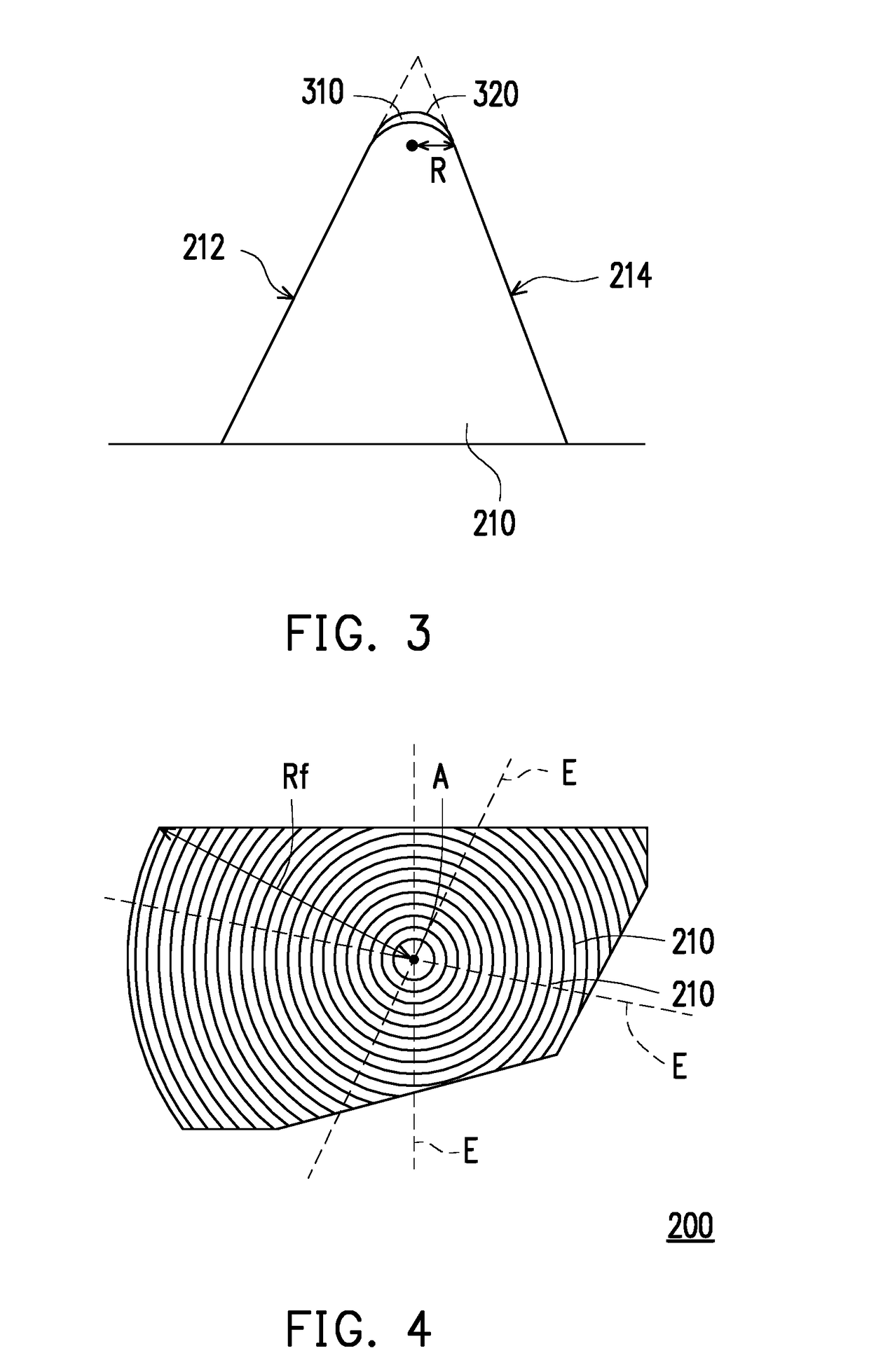
[0019]FIG. 1 is a cross-sectional schematic diagram illustrating a virtual reality display apparatus according to an embodiment of the invention. Referring to FIG. 1, a virtual reality display apparatus 100 of the present embodiment includes at least one display 110 (FIG. 1 shows two displays 110a and 110b as an example) and at least one optical assembly 120 (FIG. 1 shows two optical assemblies 120a and 120b as an example). The display 110 is adapted to provide an image beam 112 to a left eye 50a or a right eye 50b of a user. The optical assembly 120 is disposed on a transmission path of the image beam 112 and is located between the display 110 and the left eye 50a or the right eye 50b of the user. In the present embodiment, the display 110a and the display 110b respectively provide two image beams 112a and 112b, and the image beam 112a and the image beam 112b are respectively transmitted to the left eye 50a and the right eye 50b of the user via the optical assembly 120a and the opt...


PUM


Abstract

A virtual reality display apparatus includes at least one display and at least one optical assembly. The display provides an image beam to a left eye or a right eye of a user. The optical assembly is disposed on a transmission path of the image beam and located between the left eye or the right eye of the user and the display. The optical assembly includes at least one Fresnel lens including ring structures surrounding an optical axis thereof. Each of the ring structures includes an effective refraction surface and an optically non-effective surface connected to each other and arranged along a radial direction. A junction of the effective refraction surface and the optically non-effective surface has a round angle. The radius of curvature of the round angles of at least some of the ring structures of the Fresnel lens is smaller than 10 μm and larger than 0 μm.

Description

CROSS-REFERENCE TO RELATED APPLICATION[0001]This application claims the priority benefit of Taiwan application serial no. 106118268, filed on Jun. 2, 2017. The entirety of the above-mentioned patent application is hereby incorporated by reference herein and made a part of this specification.BACKGROUND OF THE INVENTIONField of the Invention[0002]The invention relates to a display apparatus, and in particular, a virtual reality display apparatus.Description of Related Art[0003]As the display technology advances, in pursuit of close-to-reality experiences, users are no longer satisfied with watching two-dimensional images. To provide users with visual entertainment of more sense of reality and stereoscopic sense, virtual reality (VR) has become a new trend in the current display technology. Virtual reality involves simulating a three-dimensional virtual scene to provide users with visual and other sensual experiences and enable users to watch three-dimensional images in real-time or ev...

Claims


Application Information

Patent Timeline
Patent Type & Authority Applications(United States)
IPC IPC(8): G02B27/01G06F3/01H04N13/00H04N13/02
CPCH04N13/106G06F3/011G02B27/0172H04N13/344G02B2027/0134G02B3/08G02B27/0018G02B2027/012G02B30/34
Inventor CHIU, YI-JUNGSHIH, WEI-KUOLEE, YI-HUANGHUANG, SHIH-TING
Owner ACER INC
Why Eureka
Eureka Blog
Learn More