Image Inspection Apparatus

a technology of image inspection and apparatus, which is applied in the field of image inspection apparatus, can solve the problems of user burden, complicated operation, and difficulty in further improvement of defect inspection accuracy, and achieve the effects of high accuracy of contour specification, improved defect inspection accuracy, and simple operation

Inactive Publication Date: 2018-12-06
KEYENCE
View PDF2 Cites 10 Cited by
  • Summary
  • Abstract
  • Description
  • Claims
  • Application Information

AI Technical Summary

Benefits of technology

[0007]The present invention has been devised in view of such points, and an object of the present invention is to make it possible to highly accurately specify a contour even with simple operation and further improve accuracy of a defect inspection.
[0017]According to the present invention, it is possible to highly accurately specify a contour with simple operation and further improve accuracy of a defect inspection.

Problems solved by technology

In particular, when the inspection target object has a complicated contour, operation for specifying the contour is complicated or troublesome and an operation burden is imposed on a user.
It is also likely that the contour is specified differently depending on the skill or the like of the user and further improvement of accuracy of the defect inspection is difficult.

Method used


Image

  • Image Inspection Apparatus
  • Image Inspection Apparatus
  • Image Inspection Apparatus

Examples


first embodiment

Overall Configuration of an Image Inspection Apparatus 1

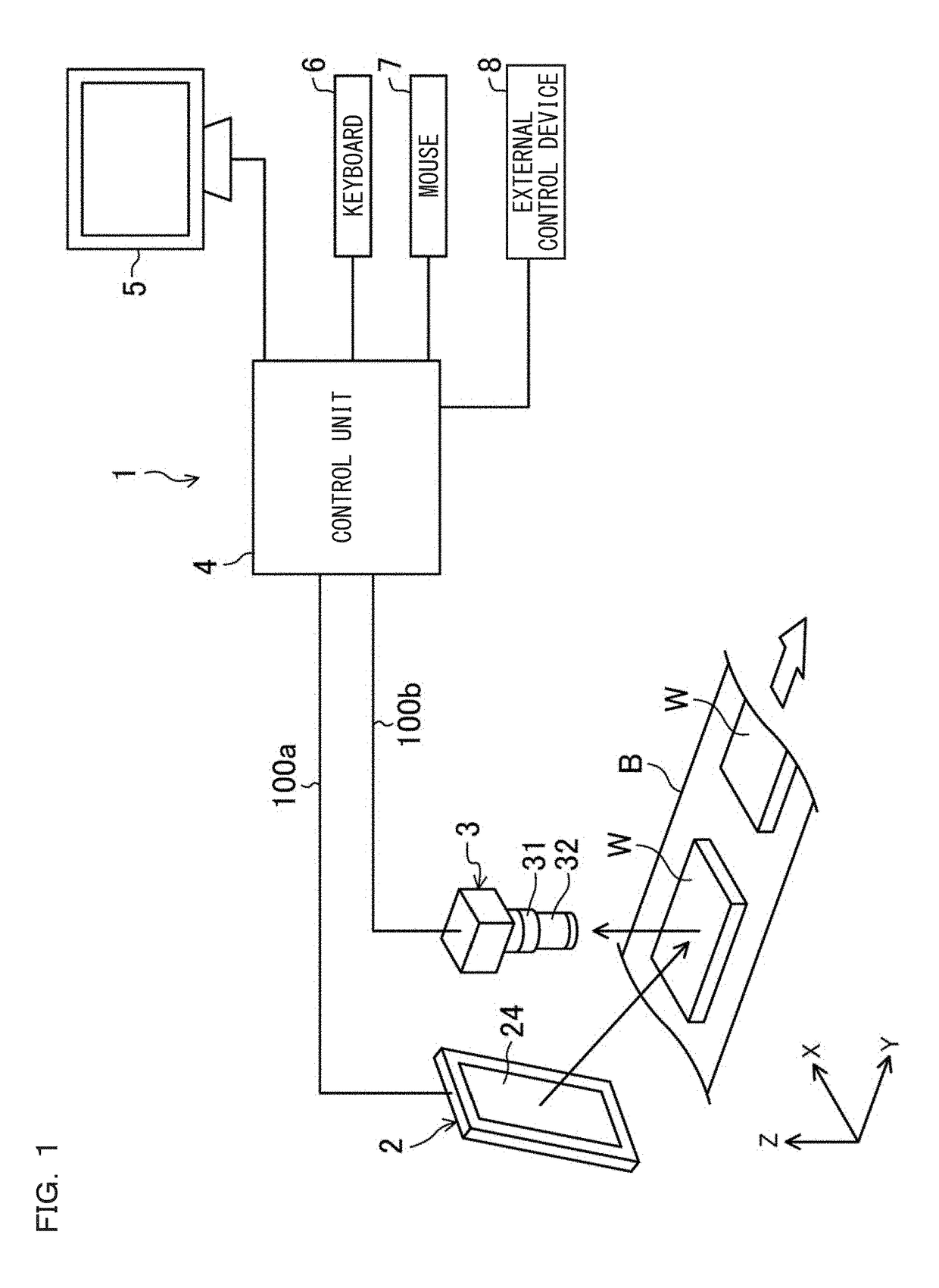
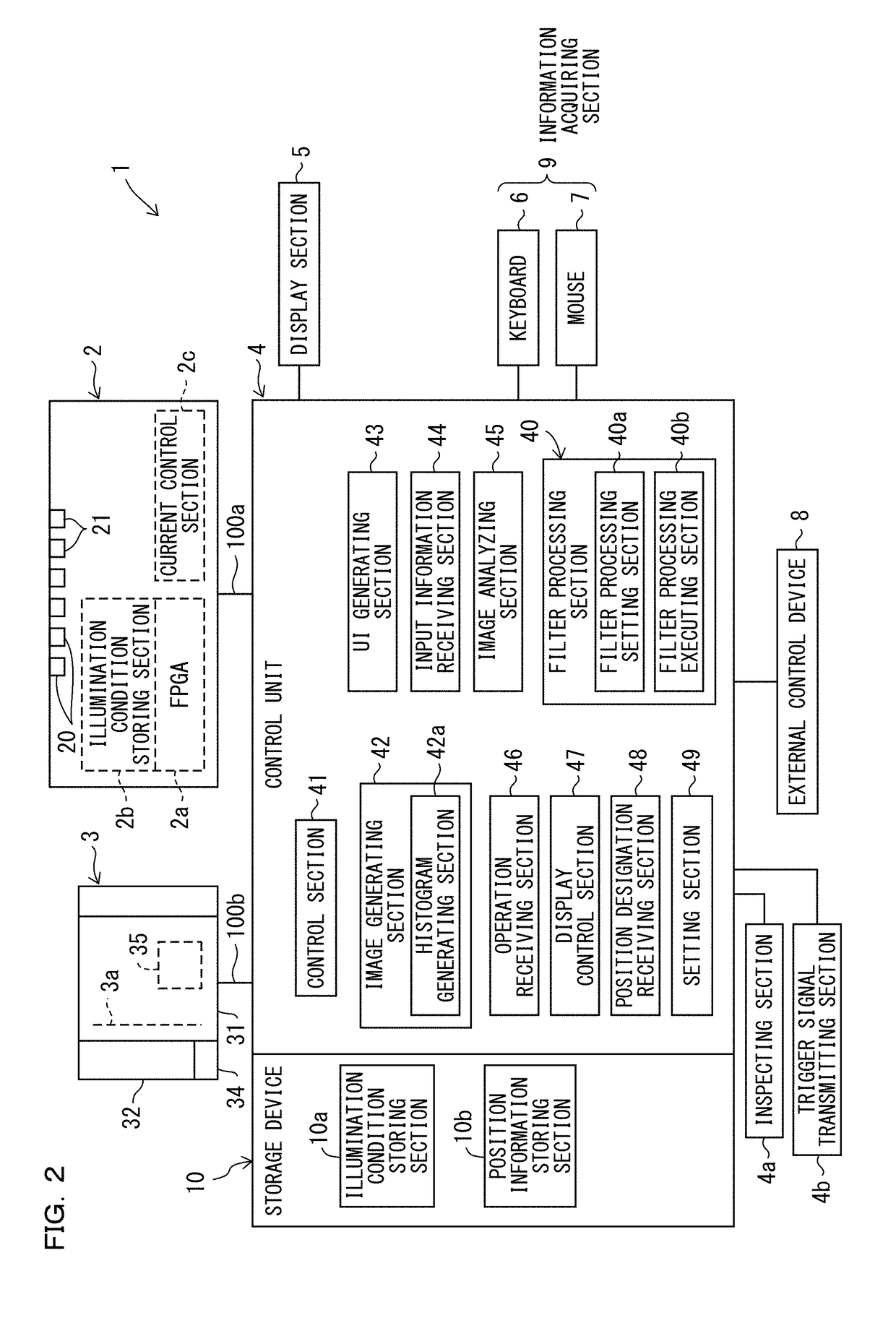
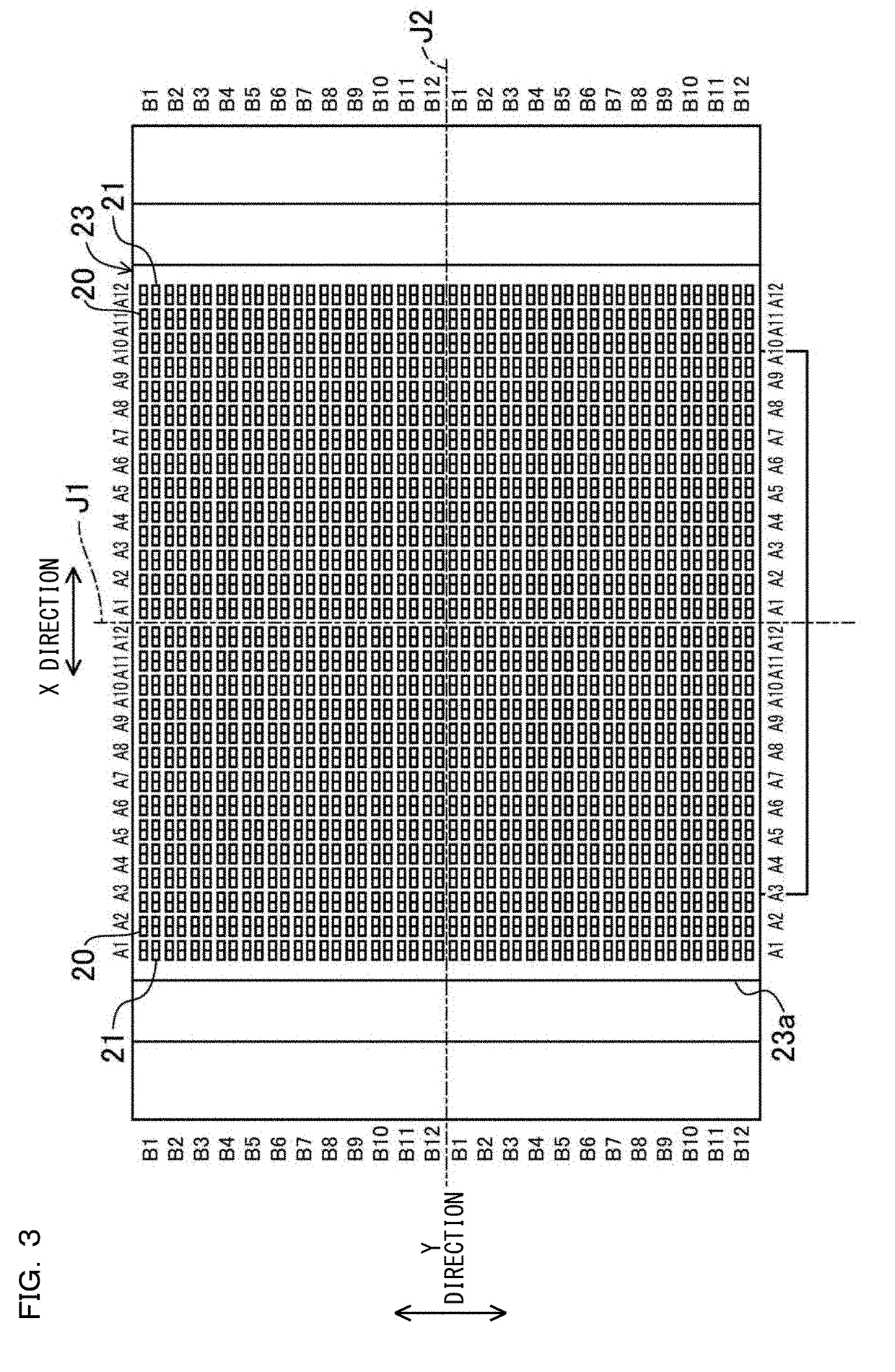
[0081]FIG. 1 is a diagram schematically showing an operation state of an image inspection apparatus 1 according to an embodiment of the present invention. The image inspection apparatus 1 is configured to inspect a defect of work W using an image obtained by imaging the work W (an inspection target object) moving in one direction. Specifically, the image inspection apparatus 1 includes at least a, pattern light illuminating section 2 that executes pattern light illumination for irradiating a plurality of pattern lights on the work W, an imaging section 3, a control unit 4, a display section 5, a keyboard 6, and a mouse 7. The image inspection apparatus 1 can include devices other than these devices. For example, an external control device 8 configured from a programmable logic controller (PLC) or the like is connected to the control unit 4. The external control device 8 may configure a part of the image inspection apparatus 1. ...

second embodiment

[0277]In the first embodiment, the function of performing the deflectometry processing on the obtained luminance image to thereby generate an image for inspection is explained. However, besides the deflectometry processing function, for example, a function of generating an image for inspection making use of a photometric stereo method can also be imparted to the image inspection apparatus 1 according to the present invention.

[0278]Concerning generating an image for inspection making use of the photometric stereo method, differences from the first embodiment are explained in detail with reference to FIG. 38. The same sections as the sections in the first embodiment are denoted by the same reference numerals and signs and explanation of the sections is omitted.

[0279]The image inspection apparatus 1 according to the second embodiment can be configured the same as, for example, the image inspection apparatus disclosed in Japanese Patent Application Laid-Open No. 2015-232486. That is, th...

third embodiment

[0287]FIG. 39 is a block diagram of the image inspection apparatus 1 according to a third embodiment of the present invention. The third embodiment is different from the first embodiment in that the image inspection apparatus 1 includes an edge generating section 500. However, the other sections are the same as the sections in the first embodiment. Therefore, the same sections as the sections in the first embodiment are denoted by the same reference numerals and signs and explanation of the sections is omitted. The different sections are explained in detail.

[0288]When inspection of the work W is performed, for example, a user sometimes desires to perform a defect inspection of a contour having a complicated shape or perform a defect inspection in a specific region having a complicated shape. In such a case, a contour needs to be accurately extracted on an image for inspection. The edge generating section 500 is a section for generating a contour of the work W on a screen displayed o...


PUM


Abstract

To make it possible to highly accurately specify a contour even with simple operation and further improve accuracy of a defect inspection. A plurality of edge detection regions are set on an image for inspection. A contour segment is formed in each of the edge detection regions. Connection processing for connecting an end portion of one contour segment and an end portion of another contour segment is repeatedly executed to form a closed region. A defect inspection of an inspection target object is executed with the closed region set as an inspection target region.

Description

CROSS-REFERENCE TO RELATED APPLICATIONS[0001]The present application claims foreign priority based on Japanese Patent Application No. 2017-107441, filed May 31, 2017, the contents of which is incorporated herein by reference.BACKGROUND OF THE INVENTION1. Field of the Invention[0002]The present invention relates to an image inspection apparatus that inspects a defect of an inspection target object using an image obtained by imaging the inspection target object.2. Description of Related Art[0003]There has been known an image inspection apparatus that inspects a defect such as a burr or a dent from an image obtained by imaging an inspection target object (see, for example, JP-A-2009-186338 (Patent Literature 1)).[0004]The image inspection apparatus described in Patent Literature 1 is configured to acquire an image including a contour of the inspection target object, set a segment having a predetermined width in a target region including a part of the contour, sequentially move the segm...

Claims


Application Information

Patent Timeline
Patent Type & Authority Applications(United States)
IPC IPC(8): G06T7/00G06K9/62G06T7/13G06T7/12G06V10/44G06V10/46
CPCG06T7/0004G06K9/6204G06T7/13G06T7/12G06T2207/10012G06T2207/20076G06T2207/20096G06T2207/20104G06T2207/30164G06T2207/10141G06T7/194G06T7/136G06V10/44G06V10/752G06V10/46
Inventor NAKAO, MASASHI
Owner KEYENCE
Why Eureka
Try Eureka