Methods and apparatus for detecting motion via optomechanics

Active Publication Date: 2018-12-13
YUKKA MAGIC LLC
View PDF0 Cites 22 Cited by
  • Summary
  • Abstract
  • Description
  • Claims
  • Application Information

AI Technical Summary

Benefits of technology

[0066]In some embodiments, the bladder includes at least one fluid reservoir containing a fluid and a plurality of artificial blood vessels in fluid communication with the at least one fluid reservoir. Compression of the bladder due to subject motion causes the fluid to be forced from the at least one fluid reservoir into the artificial vessels, thereby creating pressure within the bladder that can be detected by the pressure sensor. Such a configuration may be useful to more closely resemble that of venous blood in the body, such that the artificial structure may generate a motion noise waveform that more closely resembles that of

Problems solved by technology

Unfortunately, a biometric signal from a physiological sensor of a wearable device typically includes subject motion-related noise, and PPG sensors are particularly sensitive to motion-related noise.
Moreover, efforts to use accelerometer- or gyroscopic-based signals as motion noise references for cleaning up PPG signals have

Method used


Image

  • Methods and apparatus for detecting motion via optomechanics
  • Methods and apparatus for detecting motion via optomechanics
  • Methods and apparatus for detecting motion via optomechanics

Examples


Example

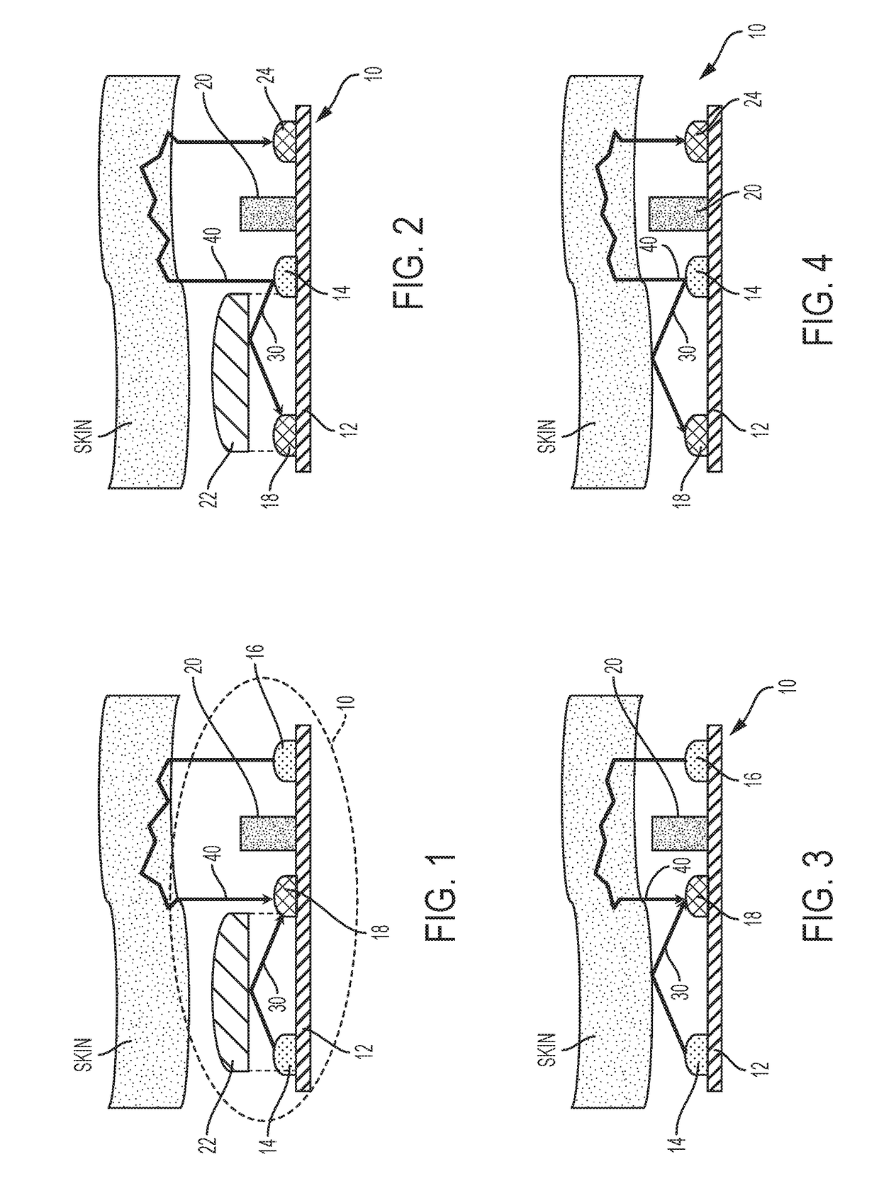
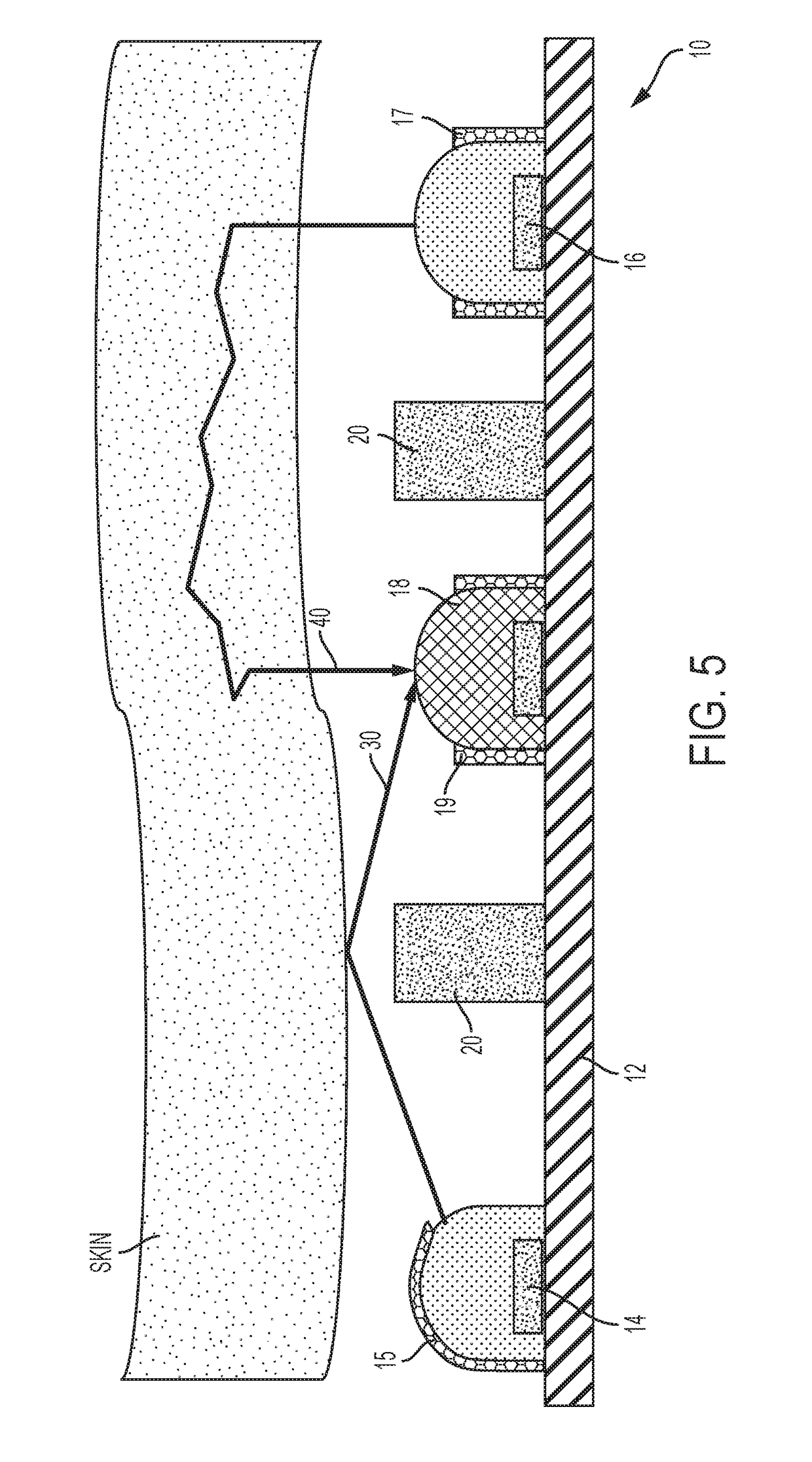
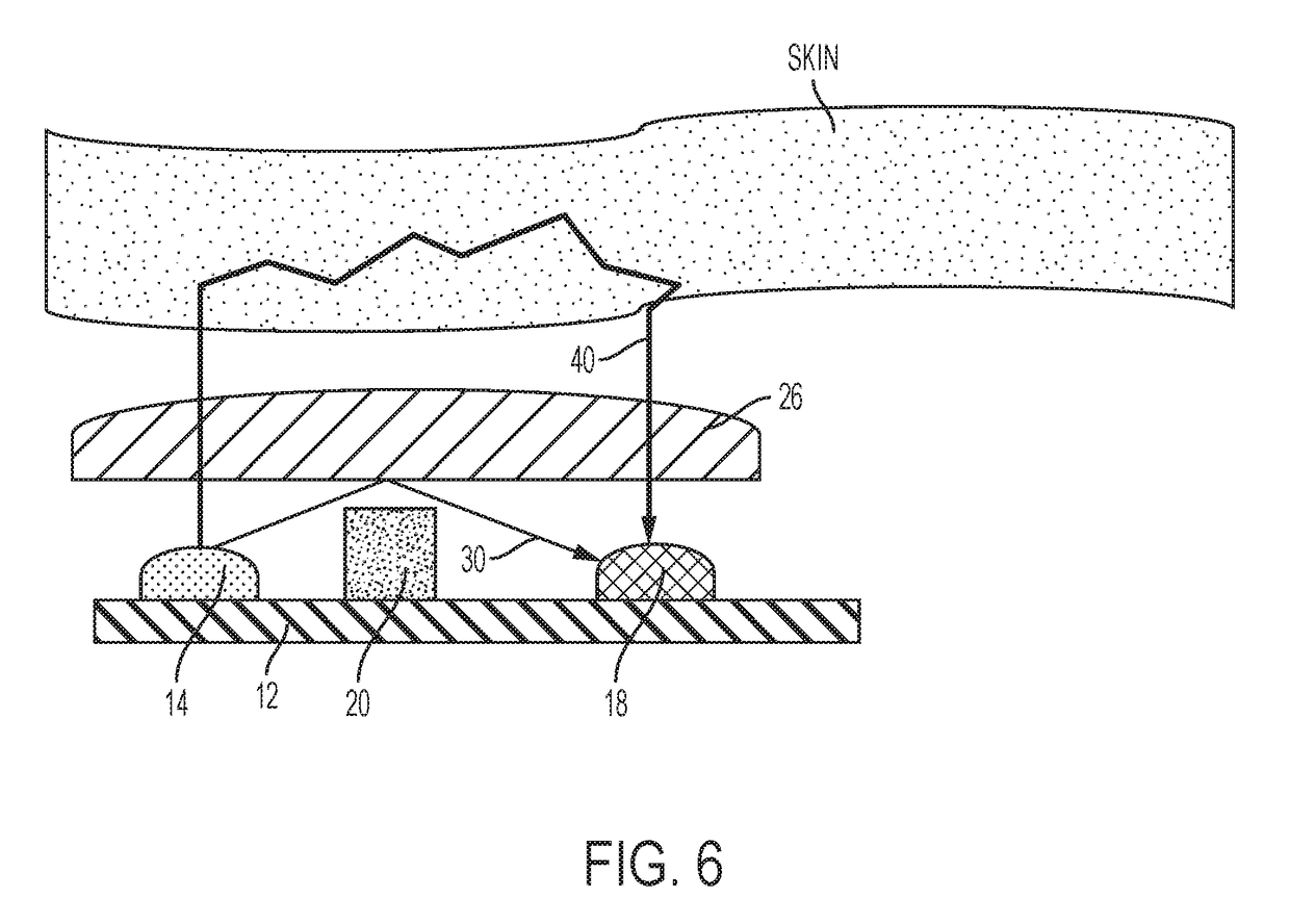
[0115]The present invention will now be described more fully hereinafter with reference to the accompanying figures, in which embodiments of the to invention are shown. This invention may, however, be embodied in many different forms and should not be construed as limited to the embodiments set forth herein. Like numbers refer to like elements throughout. In the figures, certain layers, components or features may be exaggerated for clarity, and broken lines illustrate optional features or operations unless specified otherwise. In addition, the sequence of operations (or steps) is not limited to the order presented in the figures and / or claims unless specifically indicated otherwise. Features described with respect to one figure or embodiment can be associated with another embodiment or figure although not specifically described or shown as such.

[0116]It will be understood that when a feature or element is referred to as being “on” another feature or element, it can be directly on th...


PUM


Abstract

Methods and apparatus are described for facilitating the extraction of cleaner biometric signals from biometric monitors. A motion reference signal is generated independently from a biometric signal and then the motion reference signal is used to remove motion artifacts from the biometric signal.

Description

RELATED APPLICATIONS[0001]This application claims the benefit of and priority to U.S. Provisional Patent Application No. 62 / 204,214 filed Aug. 12, 2015, U.S. Provisional Patent Application No. 62 / 257,502 filed Nov. 19, 2015, and U.S. Provisional Patent Application No. 62 / 345,579 filed Jun. 3, 2016, the disclosures of which are incorporated herein by reference as if set forth in their entireties.FIELD OF THE INVENTION[0002]io The present invention relates generally to monitoring devices and methods and, more particularly, to monitoring devices and methods for measuring physiological information.BACKGROUND OF THE INVENTION[0003]Wearable devices capable of monitoring physiological information, such as heart rate, are increasingly being used. These devices come in various form factors, including devices configured to be worn at the ear or at other locations of the body, and including devices carried or worn by a person, such as smartphones, etc. U.S. Pat. Nos. 8,652,040, 8,700,111, 8,64...

Claims


Application Information

Patent Timeline
IPC IPC(8): A61B5/00A61B5/1455A61B5/024
CPCA61B5/721A61B5/6804A61B5/14551A61B5/7214A61B5/02416A61B2562/146A61B2562/185A61B5/14552A61B5/6802A61B5/6817A61B5/6843A61B5/6898A61B5/0059A61B5/0261A61B5/6844A61B5/01A61N5/0625A61N5/0613A61N2005/0628A61N2005/0645
Inventor WALTER, JONATHAN T.JUST, STEVEN MATTHEWWAGNER, WOLFGANGLEBOEUF, STEVEN FRANCESTUCKER, JESSE BERKLEYAUMER, MICHAEL EDWARDESCHBACH, LAWRENCE CHRISTOPHERLONG, SETH
Owner YUKKA MAGIC LLC
Why Eureka
Try Eureka