Systems and Methods For Stimulating A Subterranean Formation

Inactive Publication Date: 2019-08-08
KELLER STUART R
View PDF9 Cites 0 Cited by
  • Summary
  • Abstract
  • Description
  • Claims
  • Application Information

AI Technical Summary

Benefits of technology

[0011]The present disclosure is directed to systems and methods for providing a stimulant fluid to a subterranean formation. These systems and methods may include apportioning a production liner assembly into a plurality of treatment zones and providing a stimulant fluid to at least an initial treatment zone of the plurality of treatment zones. Apportioning the production liner assembly into the plurality of treatment zones may include utilizing a longitudinal flow control device to fluidly isolate at least a first portion of the plurality of treatment zones from at least a second portion of the plurality of treatment zones and/or placing an outlet of a stimulant fluid supply device proximal a selected treatment zone of the plurality of treatment zones. Providing the stimulant fluid may include providing the stimulant fluid through one or more outflow control devices.
[0012]In some embodiments, the longitudinal flow control devices may include ball and seat assemblies and the apportioning may include supplying a ball to a seat assembly to provide the fluid isolation. In some embodiments, the outflow control devices may include an outflow check valve adapted to facilitate flu

Problems solved by technology

Subterranean wells, such as extended reach subterranean wells, may present unique challenges associated with construction, completion, stimulation, and/or production.
When stimulating a subterranean well, it may be difficult to stimulate the entire subterranean well simultaneously.
This may be especially challenging when the subterranean well is an extended reach well and/or when the subterranean well includes a plurality of UEDs.
However, this approach may only supply stimulant fluid to a portion of the subterranean formation that is near the UEDs and may fail to stimulate portions of the subterranean formation that are not near a UED.
However, the use of t

Method used


Image

  • Systems and Methods For Stimulating A Subterranean Formation
  • Systems and Methods For Stimulating A Subterranean Formation
  • Systems and Methods For Stimulating A Subterranean Formation

Examples


Embodiment Construction

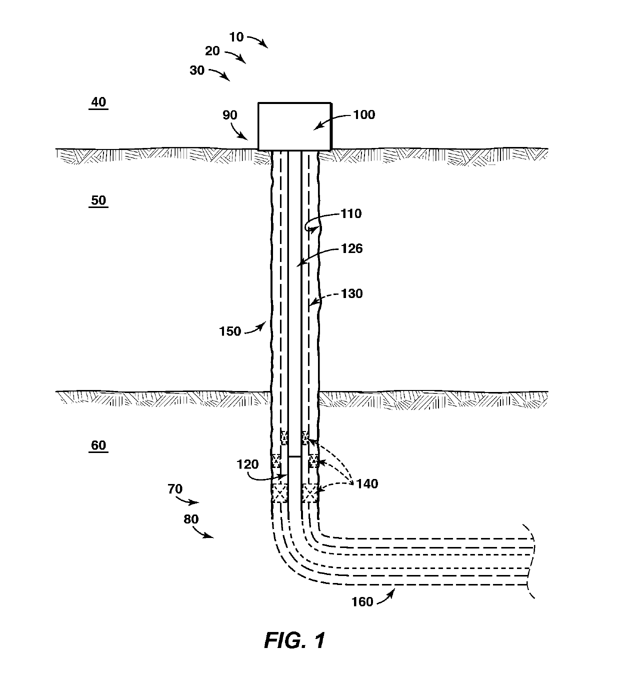
[0022]FIG. 1 provides a schematic, cross-sectional view of an illustrative, non-exclusive example of a subterranean well 10 that may be utilized with the systems and methods according to the present disclosure. Subterranean well 10, which may include, or be, a hydrocarbon well 20, an oil well 30, and / or a natural gas well, provides a hydraulic, or fluid, connection between a surface region 40 and a subsurface region 50, such as between the surface region and a subterranean formation 60. Subterranean formation 60 may include a reservoir 70 that may contain or include a reservoir fluid 80.

[0023]Subterranean well 10 further may include a production control assembly 100 that is associated with a wellhead 90 and which is adapted or configured to control a supply of stimulant fluids from the wellhead to reservoir 70 and / or the production of reservoir fluid 80 from the reservoir to the wellhead. The subterranean well further includes a wellbore 110 that may contain production liner assembl...


PUM


Abstract

Systems and methods for supplying a stimulant fluid to a subterranean formation, including apportioning a production liner assembly into a plurality of treatment zones and providing the stimulant fluid to at least an initial treatment zone of the plurality of treatment zones. Apportioning the production liner assembly into the plurality of treatment zones may include utilizing a longitudinal flow control device to fluidly isolate at least a first portion of the plurality of treatment zones from at least a second portion of the plurality of treatment zones and/or placing an outlet of a stimulant fluid supply device proximal a selected treatment zone. May include providing the stimulant fluid through one or more outflow control devices. The systems and methods also may include receiving a reservoir fluid through one or more inflow control devices.

Description

CROSS REFERENCE TO RELATED APPLICATIONS[0001]This application claims the benefit of U.S. Provisional Application 61 / 425,121, filed Dec. 20, 2010.FIELD OF THE DISCLOSURE[0002]The present disclosure is directed to systems and methods for stimulating a subterranean formation.BACKGROUND OF THE DISCLOSURE[0003]Subterranean wells, such as extended reach subterranean wells, may present unique challenges associated with construction, completion, stimulation, and / or production. This may be due to a variety of factors, including a length of the subterranean well, variations in the subterranean formation(s) that may be experienced along the length of the subterranean well, and / or variations in the reservoir fluid(s) that may be encountered along the length of the subterranean well. Because of these and other factors, construction, completion, stimulation, and / or production operations may be improved, simplified, streamlined, and / or made more efficient if a flow of fluid between the subterranea...

Claims


Application Information

Patent Timeline
IPC IPC(8): E21B43/14E21B43/26E21B34/14
CPCE21B33/124E21B43/12E21B43/26E21B34/14E21B43/14E21B43/27E21B34/142
Inventor KELLER, STUART R.
Owner KELLER STUART R
Why Eureka
Try Eureka