
Hydraulic motor control system and method

Pending Publication Date: 2022-02-03
DEERE & CO
View PDF0 Cites 0 Cited by
  • Summary
  • Abstract
  • Description
  • Claims
  • Application Information

AI Technical Summary

Benefits of technology

The work machine has a pump and motor that work together to adjust the current. The controller controls the movement of a valve that helps to move fluid to the motor. This allows for smoother operation of the work machine.

Problems solved by technology

In such hydraulic systems, there is often an undesired compromise between cost, hydraulic efficiency, mechanical and volumetric change over time of the hydraulic system components, and precision of motor speed control.
However, problems may arise, for example, since the fixed displacement motor experiences various loading conditions, and therefore, demands varying flow rates of fluid.
Other problems may arise as well.
The varying output of fluid flow from the pump results in downstream flow variability to the fixed displacement motor.
Additionally, as the hydraulic system operates over time, the mechanical and volumetric efficiencies of the motor and the pump, for example, can vary, which changes the flow rate of fluid to the motor, thereby changing the motor speed in any undesired fashion.
Similarly, a variation in fluid temperature or viscosity can impact the motor speed in an undesired fashion, if not accounted for.

Method used


Image

  • Hydraulic motor control system and method
  • Hydraulic motor control system and method
  • Hydraulic motor control system and method

Examples


Embodiment Construction

[0034]The embodiments of the present disclosure described below are not intended to be exhaustive or to limit the disclosure to the precise forms in the following detailed description. Rather, the embodiments are chosen and described so that others skilled in the art may appreciate and understand the principles and practices of the present disclosure.

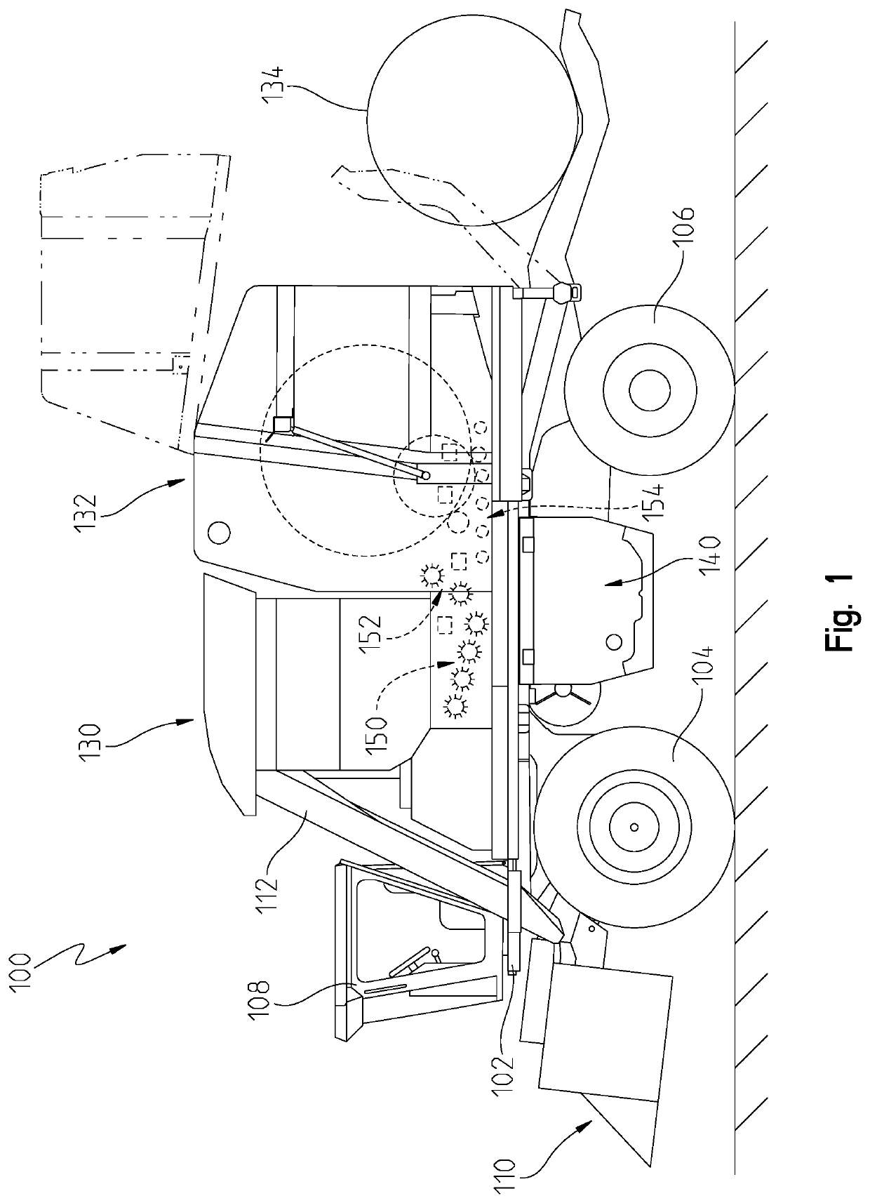
[0035]Referring now to FIG. 1, a cotton harvester 100 is shown having a main frame 102 supported above the ground by front wheels 104 and rear wheels 106. An operator station or cab 108 is supported at the front end of the main frame 102 above cotton harvesting units 110, which remove cotton from plants and direct the removed cotton into an air duct system 112 toward an accumulator system 130.

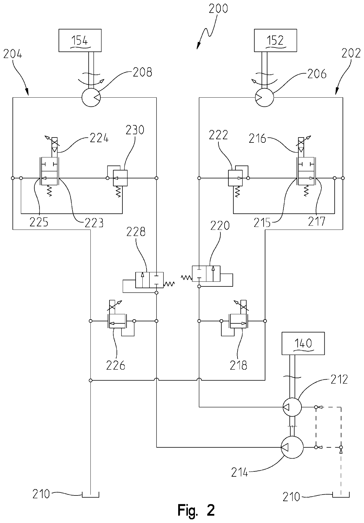
[0036]In the illustrative embodiment, the accumulator system 130 is coupled to the main frame 102 behind the cab 108. The accumulator system 130 stores cotton, which is then processed by a series of subassemblies (e.g., 150, 152, 154). The subassem...


PUM


Abstract

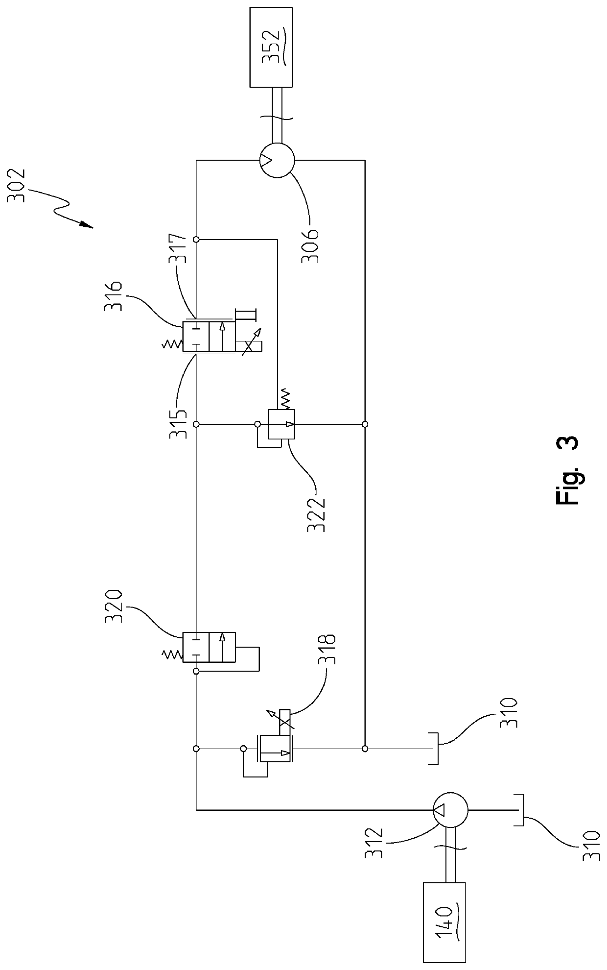
An electrohydraulic system for a work machine includes a pump, a motor fluidly coupled to the pump, a subassembly driven by the motor, and a rate-control valve fluidly coupled to the pump and the motor. The rate-control valve is movable through a range of positions. A present speed of the motor is proportional to a present position of the rate-control valve. The present position of the rate-control valve is adjustable by varying a current supplied to the rate-control valve. The supply of current to the rate-control valve is adjusted based on the difference between the present speed of the motor and a target speed of the motor.

Description

RELATED APPLICATIONS[0001]This application claims priority to U.S. Provisional Application Ser. No. 63 / 059,646, filed Jul. 31, 2020, the disclosure of which is hereby incorporated by reference in its entirety.FIELD OF THE DISCLOSURE[0002]The present disclosure relates to a work machine such as a cotton harvester and, in particular, to an electrohydraulic system and method for a work machine such as a cotton harvester.BACKGROUND OF THE DISCLOSURE[0003]Subassemblies of work machines, such as a feeder assembly and a beater assembly of a cotton harvester, are often driven by hydraulic motors and pumps. In hydraulic systems having a pump and a motor, the pump facilitates fluid flow to the motor. In such hydraulic systems, there is often an undesired compromise between cost, hydraulic efficiency, mechanical and volumetric change over time of the hydraulic system components, and precision of motor speed control.[0004]A hydraulic system with a fixed displacement motor and a fixed displaceme...

Claims


Application Information

Patent Timeline
IPC IPC(8): A01F15/08F04B19/04F04B49/20F04B23/04A01D46/08A01F15/10
CPCA01F15/085F04B19/04A01F15/106F04B23/04A01D46/08F04B49/20A01D46/085F15B11/17F15B13/06F15B21/02F15B2211/20538F15B2211/20576F15B2211/78F04B17/05A01D69/03
Inventor WALLESTAD, STEVEN D.CRACRAFT, MARK A.NOONAN, JAMES T.
Owner DEERE & CO
Learn More