
Self cooling motor system

Inactive Publication Date: 2012-09-11
HOLMES JEREMY
View PDF32 Cites 3 Cited by
  • Summary
  • Abstract
  • Description
  • Claims
  • Application Information

AI Technical Summary

Benefits of technology

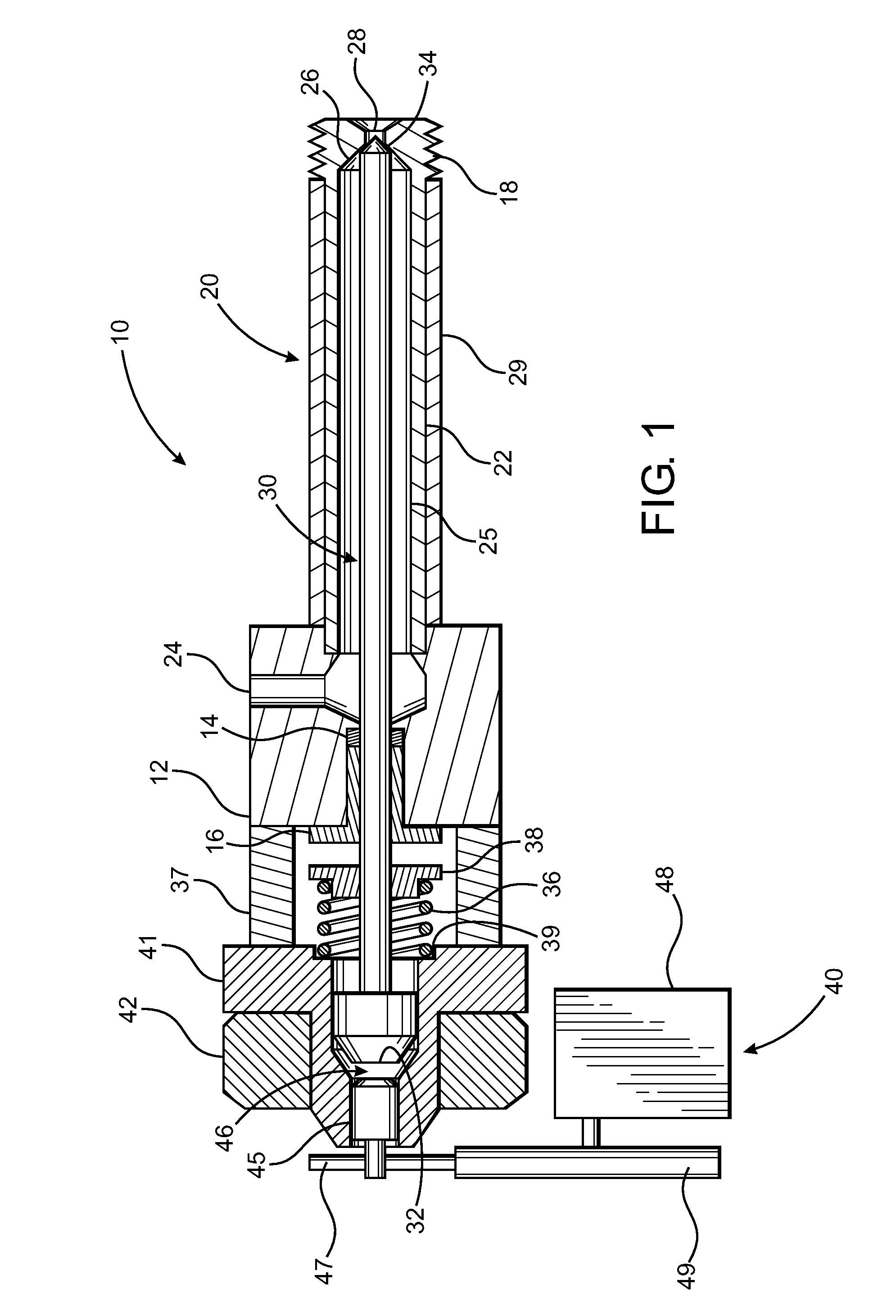
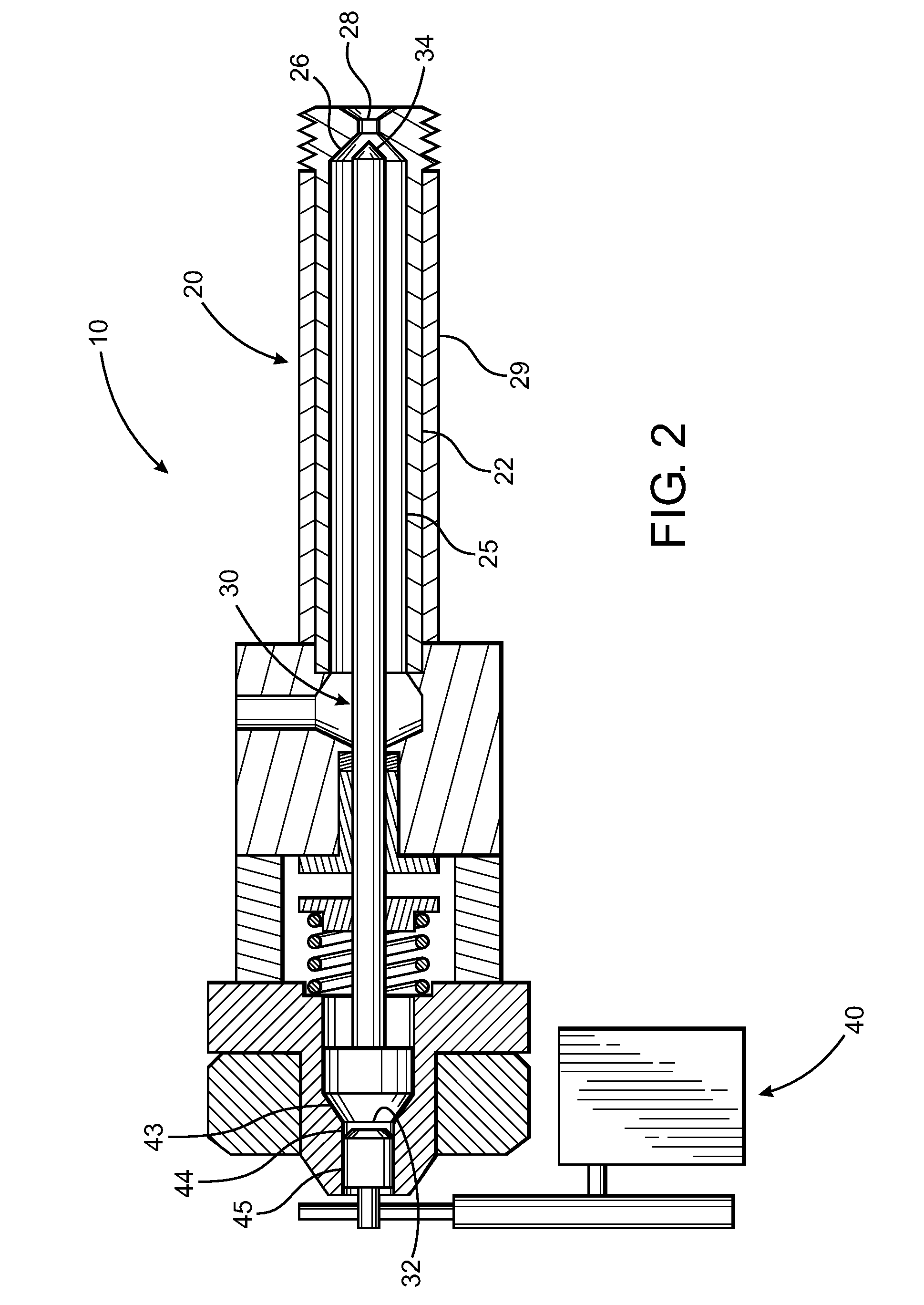
[0015]The universal injection valve assembly of the present invention further comprises an actuation assembly, wherein the actuation assembly includes an actuator. The actuator is cooperatively disposed to at least temporarily displace the control member out of the operative position. In at least one embodiment of the present invention, the actuation assembly also includes an induction mechanism which is structured to at least temporarily dispose the actuator into an energized state. Furthermore, in this embodiment, the control member at least partially comprises material which is attracted to the actuator in the energized state, thereby facilitating the displacement of the control member from the operative position.
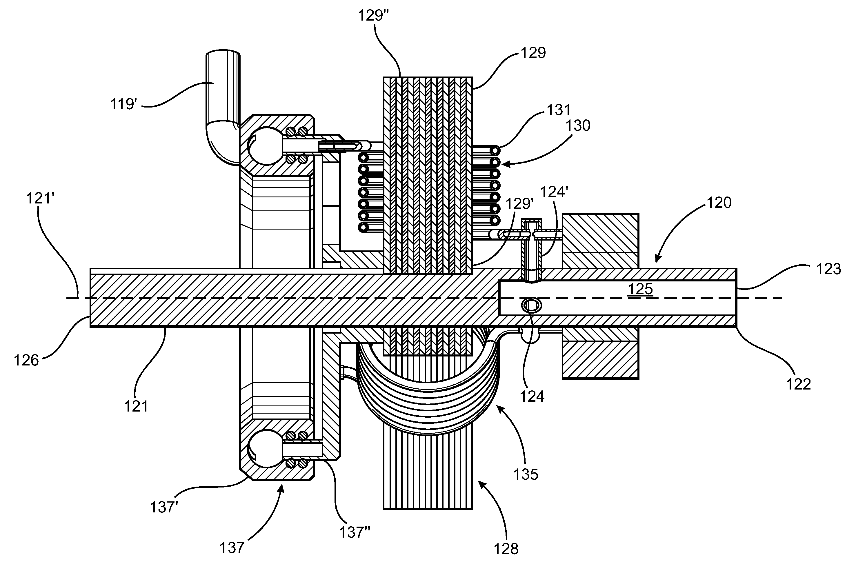
[0017]An armature assembly is mounted to the shaft and is structured to rotate with the shaft, the armature assembly having at least one pole extending outwardly and substantially perpendicular to the shaft. In at least one embodiment, the armature assembly comprises a plurality of poles extending outwardly from the shaft. Each pole has a proximal end disposed adjacent the shaft and a distal end disposed outwardly from the shaft. The internally cooled motor assembly further comprises a winding assembly including at least one winding affixed to the armature assembly, however in at least one embodiment, the winding assembly comprises a plurality of windings. More in particular, the least one winding is disposed in an overlying relation to at least one pole of the armature assembly. Each winding has an inlet aperture, an outlet aperture, and a fluid passage extending lengthwise therethrough to permit the flow of a fluid heat transfer media through the winding. The flow of the fluid heat transfer media though the winding(s) effectively removes sufficient heat from the winding(s) to allow the internally cooled motor assembly to operate efficiently, without reliance on additional external energy resources in order to maintain operation within the prescribed temperature range, thus providing additional, overall operating efficiency by eliminating external energy related operating costs. Further, in at least one embodiment, the internally cooled motor assembly is “self pumping”, furthering the reduction and / or elimination of external energy related operating costs, and further improving the overall operating efficiency.
[0018]To facilitate the flow of the fluid heat transfer media though the windings, the internally cooled motor assembly also includes an inlet fluid transfer slip ring assembly interconnected to an open end of the shaft and disposed in a fluid transferring configuration with an inlet of the shaft. The shaft also having an outlet interconnected to the inlet aperture of each winding and disposed in a fluid transferring relation therewith. The internally cooled motor assembly also includes an outlet fluid transfer slip ring assembly disposed in a fluid transferring orientation to the outlet aperture of each winding, wherein the outlet aperture of each winding is disposed proximate the distal end of a corresponding pole extending outwardly from the shaft. Further, each winding comprises a helix configuration between its inlet and outlet apertures, the helix configuration being specifically structured such that rotation of the armature assembly at a predetermined speed creates a centrifugal force sufficient to maintain a predetermined flowrate of the fluid heat transfer media through the fluid passage of each winding, wherein a direction of flow of the fluid heat transfer media through each winding is from its inlet aperture to its outlet aperture. Moreover, flow of the fluid heat transfer media through the fluid passage of each winding at the predetermined flowrate results in a transfer of a predetermined amount of heat from each winding to the fluid heat transfer media, thereby maintaining an operating temperature of the internally cooled motor assembly within a predetermined operating range, once again, resulting in improved overall operating efficiency of the internally cooled motor assembly.

Problems solved by technology

However, to date, few of these devices have found widespread acceptance and utilization, mainly due to the complexity of handling and, more importantly, controlling the quality and / or the quantity or rate of flow of the steam.
In particular, a common pitfall of many of these devices is that the components utilized for steam generation and delivery are often related to certain operating characteristics of the engine, such as combustion, as well as intake manifold vacuum pressure, engine speed, and / or quality and quantity of high temperature radiation from operation of the engine available for steam generation.
It is primarily this factor which is believed to be the reason why these devices have not achieved widespread acceptance and utilization.
Additionally, external factors, such as adverse weather conditions, may have a particularly severe and negative impact upon the viability of adding steam to a conventional air-fuel mixture.
Under these conditions, any residual water vapor remaining in a device, or its appurtenances, intended for outdoor use, such as an automobile engine, is at risk of freezing when the engine is not operating, which could easily result in temporary blockage of flow through the steam injection device.
In more severe cases, freezing water vapor could result in the rupturing of lines, freezing of throttle plates, fittings, and / or other components of the steam injection device as the freezing water vapor expands on the inside of these components.
Thus, in spite of the numerous advantages which may be obtained from the addition of steam to a conventional air-fuel mixture, the widespread acceptance and utilization of devices structured to achieve this goal has not become a reality.
Historically, however, attempts to scale down and regulate these large scale, continuous, live steam systems in relatively small scale, intermittently operated systems, for example, a four cycle engine, have been plagued with significant efficiency losses.
It is believed that among the efficiency problems associated with the small scale systems is the energy loss of the live steam as it is acted upon by the dynamics of the small scale system.
While it is understood that dynamic losses are present in large scale systems as well, the overall impact of the energy loss of the live steam is not as significant in terms of system efficiency, due in part to the large volume of steam utilized in such systems, as it is in relatively small scale systems.
A further difficulty encountered with attempts to scale down continuous, live steam systems is the accurate control of the quantity or rate of flow of live steam to a particular component of the system.
This is a problem common to handling any compressible material, as there is a delicate balance and constant trade off between pressure, volume, and temperature.
As such, and as noted above, given that steam energy losses are directly related to the system configuration, materials of construction, insulation factors, etc., these losses are exaggerated in small scale systems, particularly due to increased frictional and thermal losses through smaller scale pipes and fittings.
In general, higher temperatures reduce the operating efficiency of an electric motor due to an increase in the resistance of the conductive windings of such motors at elevated temperatures.
In order to control the operating temperature of electric motors, and in particular, the operating temperature of the conductive windings, auxiliary temperature control systems are often implemented, which are independent of the operation of the motor, such as a fan, a forced flow radiator, or even a temperature controlled environment in which a motor operates, all of which require additional external energy resources and expenses related to the operation of an electric motors, thereby resulting in a decrease in the overall operating efficiency of the same.
Alternatively, or in combination with such auxiliary temperature control systems, high resistance conductive windings have been employed in electric motors in order to prevent runaway operating temperatures, however, the trade-off in temperature control comes in the form of a reduction in the inductive magnetic forces generated at the poles of the electric motor, thereby resulting in a reduction in the operating efficiency of the motor, which is often significant.

Method used


Image

  • Self cooling motor system
  • Self cooling motor system
  • Self cooling motor system

Examples


Embodiment Construction

[0033]As previously indicated, the present invention is directed to a universal injection valve assembly, generally shown as 10 throughout the Figures. The universal injection valve assembly 10 comprises an injector assembly, generally shown as 20, which includes a housing 22. In at least one embodiment of the present invention, the housing 22 has an elongated configuration, as illustrated in the Figures, having an adaptor 18 at one end to facilitate the connection of the universal injection valve assembly 10 to a small scale engine or other device including, but not limited to, a stirling engine or a 4-cycle steam engine. The adaptor 18 may comprise a plurality of standard size external threads, as illustrated in the Figures, such that the entire universal injection valve assembly 10 may be connected to a standard size threaded socket of the small scale engine or other device. The adapter 18 is further structured to permit direct injection of an operative fluid into a combustion ch...


PUM


Abstract

A self cooling motor system includes an internally cooled motor assembly operationally interconnected to a heat transfer assembly. The internally cooled motor assembly includes a winding assembly having one or more winding, each winding constructed of an electrically conductive material and having a fluid passage extending lengthwise therethrough. A fluid heat transfer media flows through the winding(s) while the internally cooled motor assembly is in operation, and the fluid heat transfer media is structured to remove a predetermined amount of heat from the winding(s) of the motor assembly. The fluid heat transfer media is transferred to the heat transfer assembly, where heat is dissipated from the fluid heat transfer media, reducing its temperature to a preselected exit temperature, prior to reintroduction into the winding(s) of the internally cooled motor assembly.

Description

CLAIM OF PRIORITY[0001]The present patent application is a continuation-in-part and claims priority to previously filed and U.S. patent application Ser. No. 11 / 037,583, filed on Jan. 18, 2005, which has matured into U.S. Pat. No. 7,552,715 on Jun. 30, 2009 and which is incorporated by reference herein in its entirety.BACKGROUND OF THE INVENTION[0002]1. Field of the Invention[0003]The present invention is directed to a self cooling motor system comprising an internally cooled motor assembly. Specifically, the internally cooled motor assembly comprises a winding assembly including one or more windings having a fluid passage extending lengthwise from an inlet aperture to an outlet aperture and being structured to permit a fluid heat transfer media to flow therethrough. Each winding further comprises a helix configuration structured such that centrifugal forces generated by the rotation of the motor shaft are sufficient to force the flow of fluid heat transfer media through the windings...

Claims


Application Information

Patent Timeline
IPC IPC(8): F25B31/00H02K1/32H02K9/00
CPCF02M21/0275F02M25/0225F02M31/0825F02M31/093F02M31/125F02M31/16F02M51/0614H02K9/20F02M21/0263F02M51/0671H02K1/20H02K1/32Y02T10/121Y02T10/126Y02T10/32Y02T10/12Y02T10/30
Inventor HOLMES, JEREMY
Owner HOLMES JEREMY
Learn More