
Cooling ring gear

Active Publication Date: 2017-03-02
DEERE & CO
View PDF1 Cites 5 Cited by
  • Summary
  • Abstract
  • Description
  • Claims
  • Application Information

AI Technical Summary

Benefits of technology

The patent text describes a ring gear configuration for a planetary gear set in a transmission assembly. This configuration allows for improved cooling fluid flow to components of the transmission. The ring gear has an annular body with a toothed periphery and a groove for fluid flow. The gear body has an axial flow passage section and a radial flow passage section, which allows for better cooling fluid flow. This configuration can be used in a transmission arrangement with a planetary gear set and other components. The technical effect of this patent is improved cooling efficiency for transmission components.

Problems solved by technology

Certain transmission components may be configured or located (e.g., nested within other components) such that it may be difficult to adequately deliver the cooling fluid thereto.
The tight packaging of one or more planetary gear sets within the transmission may also inhibit cooling fluid from being routed to certain components.
Since ring gears have teeth along the outer or inner annular peripheries, radial through bores of this type may interfere with the tooth profiles that may lead to stress risers in the areas of engagement, especially if the bores are not closely clocked to the tooth root.

Method used


Image

  • Cooling ring gear
  • Cooling ring gear
  • Cooling ring gear

Examples


Embodiment Construction

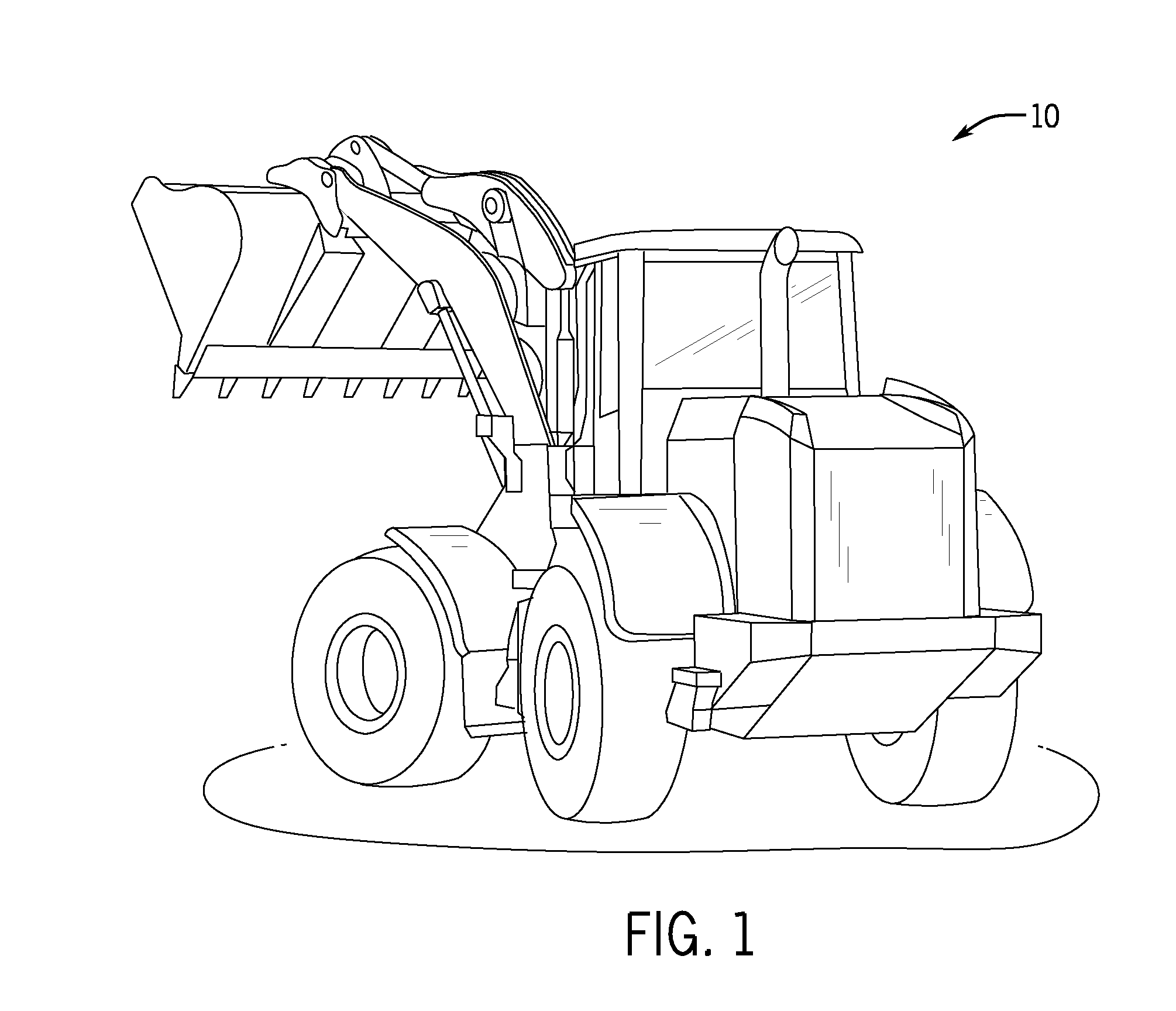
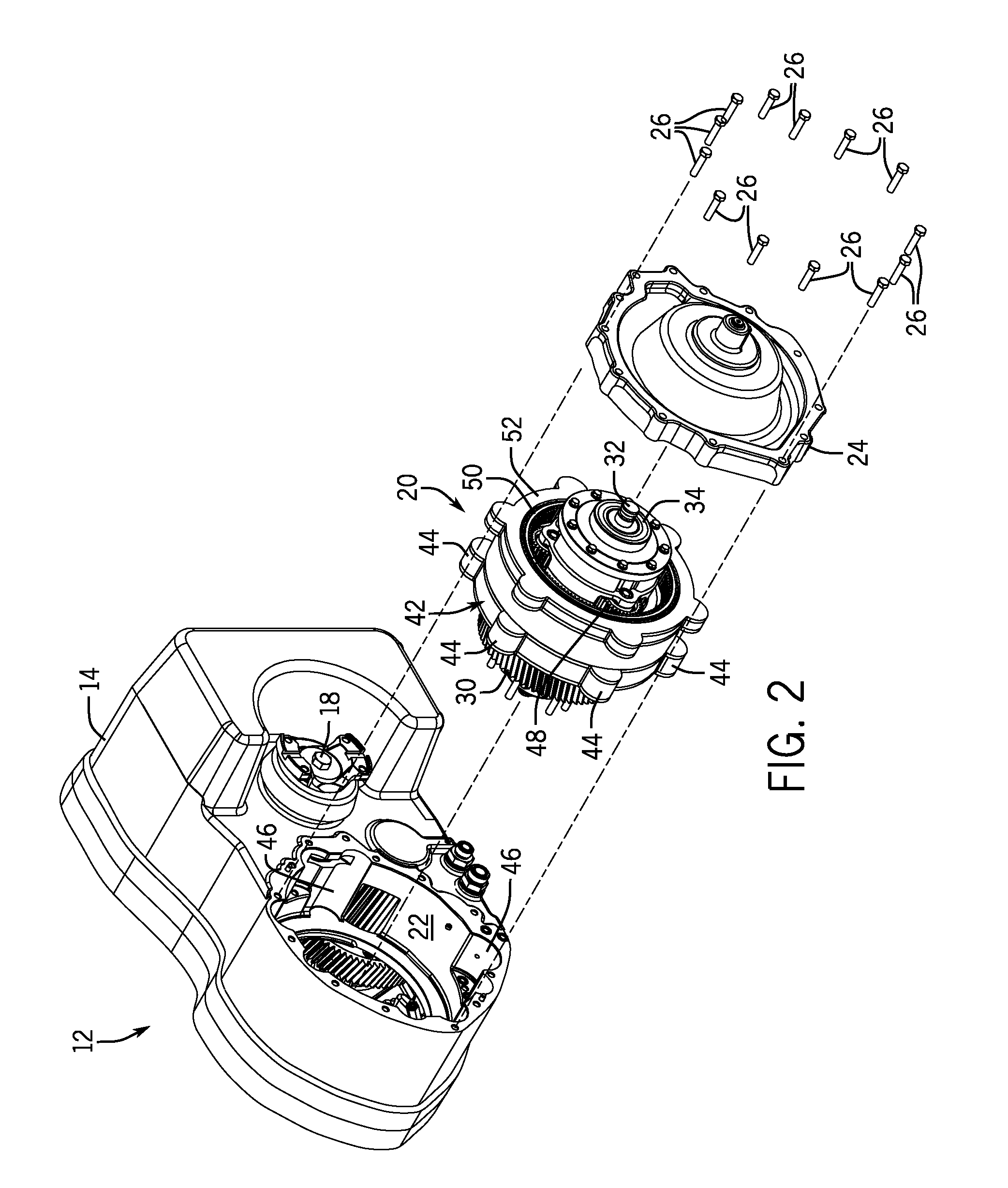
[0018]The following describes one or more example embodiments of the disclosed cooling ring gear, as shown in the accompanying figures of the drawings described briefly above. Various modifications to the example embodiments may be contemplated by one of skill in the art.

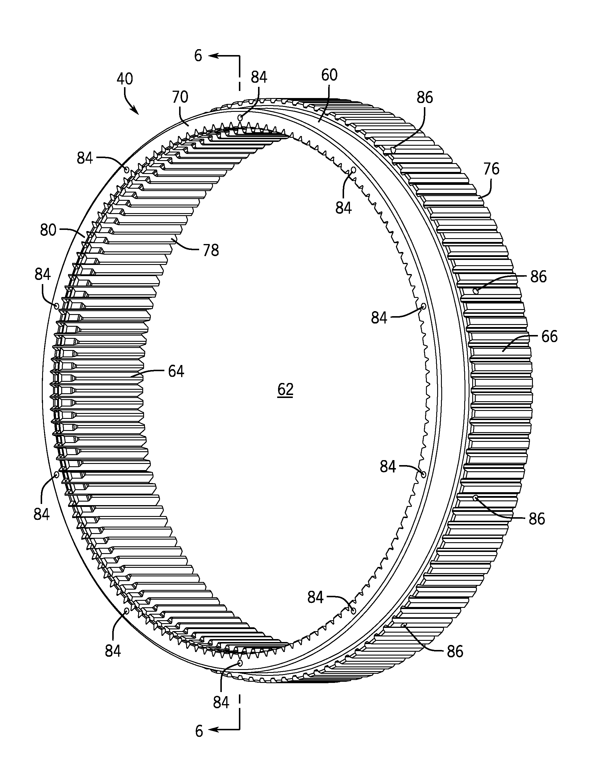
[0019]The following describes embodiments of a cooling ring gear well-suited for usage within a transmission arrangement containing a planetary gear train (referred to herein as a “planetary transmission”), such as a planetary transmission in the drivetrain of a work vehicle. The cooling ring gear includes coolant flow passages, which are strategically routed through the ring gear body to avoid penetration of the gear teeth. During high speed rotation of the cooling ring gear, oil or another coolant is conducted through the flow passages under the influence of centrifugal forces and is ultimately expelled from the ring gear at a desired discharge location. The desired discharge location may be, for example, the oute...


PUM


Abstract

A ring gear for a planetary gear set has an annular gear body with a first annular side and a second annular side concentric about a center axis. The first annular side defines a toothed periphery. The gear body may include an annular groove in the first annular side proximate a first axial side of the gear body. An axial flow passage section may extend axially into the gear body from the annular groove without intersecting the first and second annular sides. A radial flow passage section extends radially into the gear body from the second annular side to the axial flow passage section.

Description

CROSS-REFERENCE TO RELATED APPLICATION(S)[0001]Not applicable.STATEMENT OF FEDERALLY SPONSORED RESEARCH OR DEVELOPMENT[0002]Not applicable.FIELD OF THE DISCLOSURE[0003]This disclosure relates to planetary gear sets, such as used in various transmission assemblies, and components of planetary gear sets that facilitate cooling fluid flow to one or more components of the transmission.BACKGROUND OF THE DISCLOSURE[0004]Transmission assemblies of various kinds for various work vehicles may include gears and associated components arranged to contact a fluid to dissipate heat and ease engagement of mating parts. Cooling is particularly important for certain heat generating components (e.g., brakes, clutch packs and the like). Certain transmission components may be configured or located (e.g., nested within other components) such that it may be difficult to adequately deliver the cooling fluid thereto. The tight packaging of one or more planetary gear sets within the transmission may also in...

Claims


Application Information

Patent Timeline
IPC IPC(8): F16H57/04F16H1/28F16H55/17F16H57/08
CPCF16H57/0412F16H57/08F16H2055/176F16H55/17F16H1/28
Inventor MCKINZIE, KYLE K.
Owner DEERE & CO
Learn More