Tissue compression device for cardiac valve repair

a compression device and valve technology, applied in the field of tissue compression devices for cardiac valve repair, can solve the problems of insufficient space for deployment of another conventional clip, insufficient space for the required articulation, etc., and achieve the effect of increasing the size of the interior spa

Active Publication Date: 2018-12-13
EVALVE
View PDF12 Cites 86 Cited by
  • Summary
  • Abstract
  • Description
  • Claims
  • Application Information

AI Technical Summary

Benefits of technology

[0006]In one embodiment, an interventional device for compressing cardiac valve tissue at a targeted gap includes a distal member and a pair of opposing arms flexibly joined to the distal member. Each arm extends proximally from the distal member to a free end. The pair of opposing arms define an interior space between the arms for holding cardiac valve tissue. The arms have a default position and are flexibly moveable apart from one another away from the default position to increase the size of the interior space and to enable grasping of cardiac valve tissue within the interior space. The arms are configured to be biased toward the default position when moved apart from one another. In this manner, the arms provide a compressive force upon cardiac valve tissue held within the interior space.

Problems solved by technology

Such gaps may not provide sufficient space for deployment of another conventional clip, or may not provide sufficient space for the required articulation and maneuvering of a conventional clip.

Method used


Image

  • Tissue compression device for cardiac valve repair
  • Tissue compression device for cardiac valve repair
  • Tissue compression device for cardiac valve repair

Examples


Embodiment Construction

Introduction

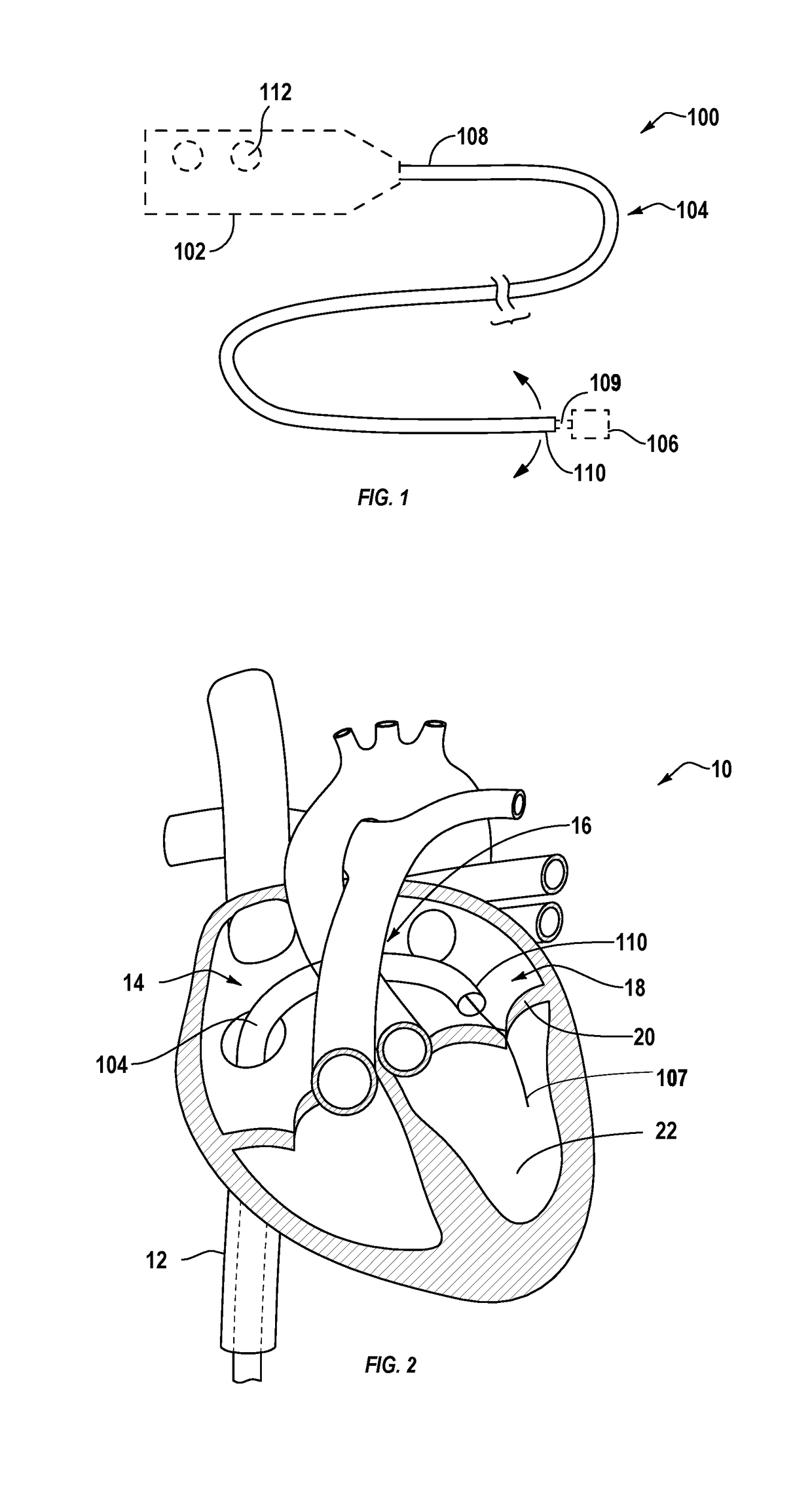
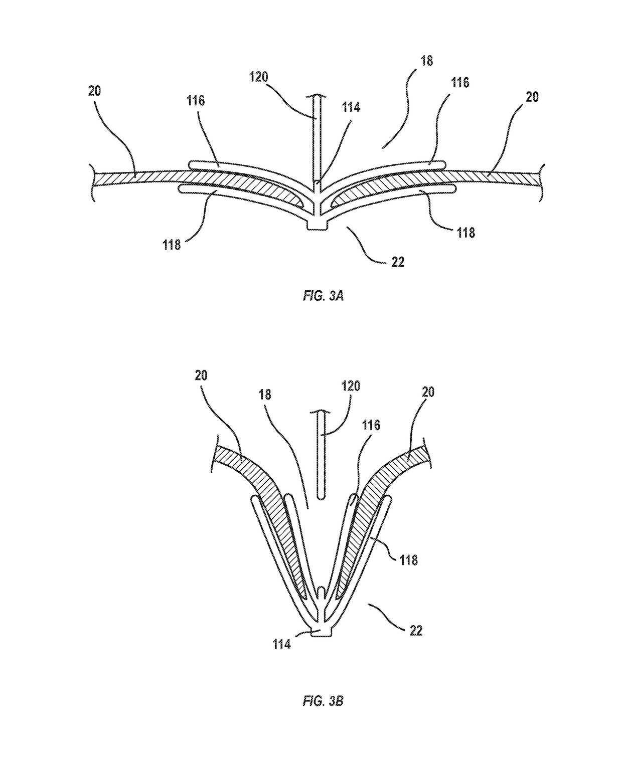
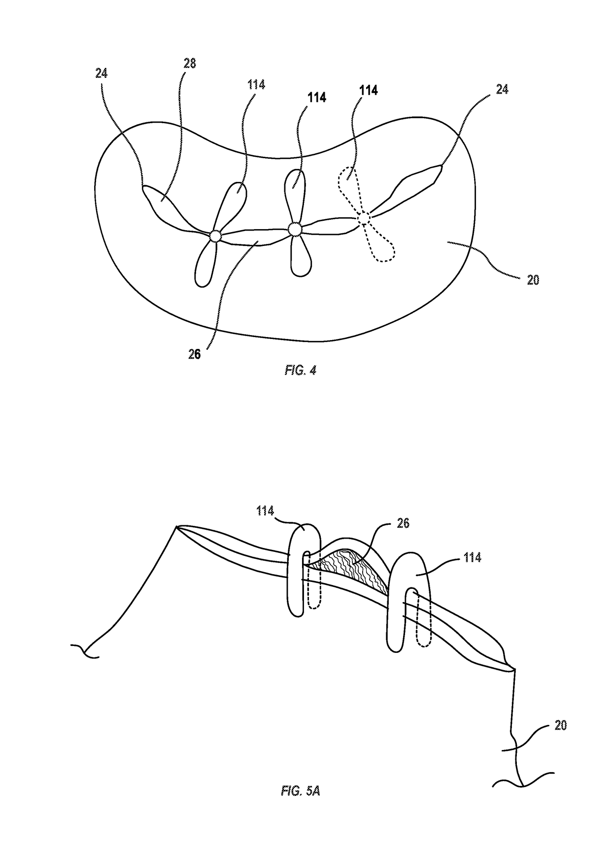
[0031]The present disclosure is directed to devices, systems, and methods for treating regurgitant leaks in cardiac valve tissue, including leaks along the cardiac valve line of coaptation. In some implementations, interventional device embodiments described herein may be deployed at gaps disposed between two previously deployed implants, or between a previously deployed implant and a valve commissure. The interventional devices may be deployed to apply a tensioning force along the line of coaptation and / or to compress captured leaflet tissue along a line orthogonal to the line of coaptation to assist in closing a targeted gap and reducing regurgitant flow through the gap.

[0032]Throughout this disclosure, many examples are described in the context of guiding a delivery system to a mitral valve. One of skill in the art will understand, however, that the described components, features, and principles may also be utilized in other applications. For example, at least some of...


PUM


Abstract

The present disclosure describes interventional devices, systems, and methods for closing a regurgitant gap in a cardiac valve. Interventional devices are configured to be deployed between two previously placed implants or between a previously placed implant and a valve commissure. The interventional devices compress captured leaflet tissue and / or apply a tensioning force along the line of coaptation to assist in closing the gap and reducing regurgitant flow through the gap.

Description

BACKGROUND[0001]The mitral valve controls blood flow from the left atrium to the left ventricle of the heart, preventing blood from flowing backwards from the left ventricle into the left atrium so that it is instead forced through the aorta for distribution throughout the body. A properly functioning mitral valve opens and closes to enable blood flow in one direction. However, in some circumstances the mitral valve is unable to close properly, allowing blood to regurgitate back into the atrium. Such regurgitation can result in shortness of breath, fatigue, heart arrhythmias, and even heart failure.[0002]Mitral valve regurgitation has several causes. Functional mitral valve regurgitation (FMR) is characterized by structurally normal mitral valve leaflets that are nevertheless unable to properly coapt with one another to close properly due to other structural deformations of surrounding heart structures. Other causes of mitral valve regurgitation are related to defects of the mitral ...

Claims


Application Information

Patent Timeline
Patent Type & Authority Applications(United States)
IPC IPC(8): A61B17/08A61F2/24A61B17/00A61B17/10
CPCA61B17/083A61F2/2463A61B2017/00243A61B17/00234A61B17/10A61F2/2466A61F2/246A61B17/1227A61B17/1285A61B2017/00783A61F2230/0054A61F2230/0091A61F2230/0045A61B2017/00477A61B2090/061
Inventor WEI, MICHAEL F.
Owner EVALVE
Why Eureka
Try Eureka