Eureka AIR delivers breakthrough ideas for toughest innovation challenges, trusted by R&D personnel around the world.

Confocal Displacement Sensor

a technology of confocal displacement and sensor, applied in the field ofconfocal displacement sensors, can solve the problems of low accuracy, decrease in intensity level after spectral dispersion, and increase in error, so as to prevent the influence of irregular reflection, and prevent the influence of measurement value from greatly fluctuating

Active Publication Date: 2018-12-13
KEYENCE
View PDF3 Cites 11 Cited by
  • Summary
  • Abstract
  • Description
  • Claims
  • Application Information

AI Technical Summary

Benefits of technology

The present invention relates to a confocal displacement sensor that improves accuracy for measuring objects that irregularly reflect light. The sensor can prevent measurement values from fluctuating excessively due to surface roughness or positional deviation of the displacement gauge. Overall, the invention provides a more accurate and reliable means of measuring these surfaces.

Problems solved by technology

Therefore, an intensity level after spectral dispersion decreases and an error increases.
Therefore, for example, accuracy is low when displacements are respectively measured in a plurality of measurement parts using a plurality of displacement gauges and flatness of the measurement object is calculated from measurement values.
Therefore, the measurement value is unstable depending on a setting state of the displacement gauge.

Method used


Image

  • Confocal Displacement Sensor
  • Confocal Displacement Sensor
  • Confocal Displacement Sensor

Examples


first embodiment

Confocal Displacement Sensor 1

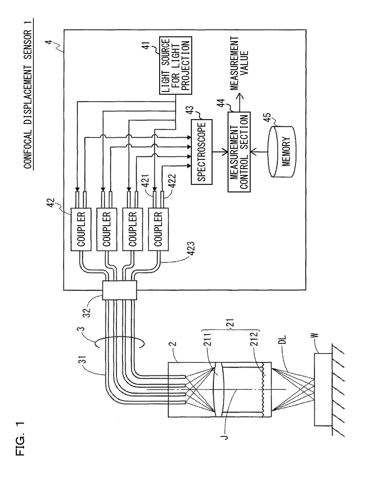
[0045]FIG. 1 is a system diagram showing a configuration example of a confocal displacement sensor 1 according to a first embodiment of the present invention. The confocal displacement sensor 1 is an optical measurement device configured by a head unit 2, a fiber cable 3, and a control device 4. The optical measurement device respectively receives reflected lights from a measurement object W when a plurality of detection lights DL are emitted from the head unit 2 and measures displacement of the measurement object W.

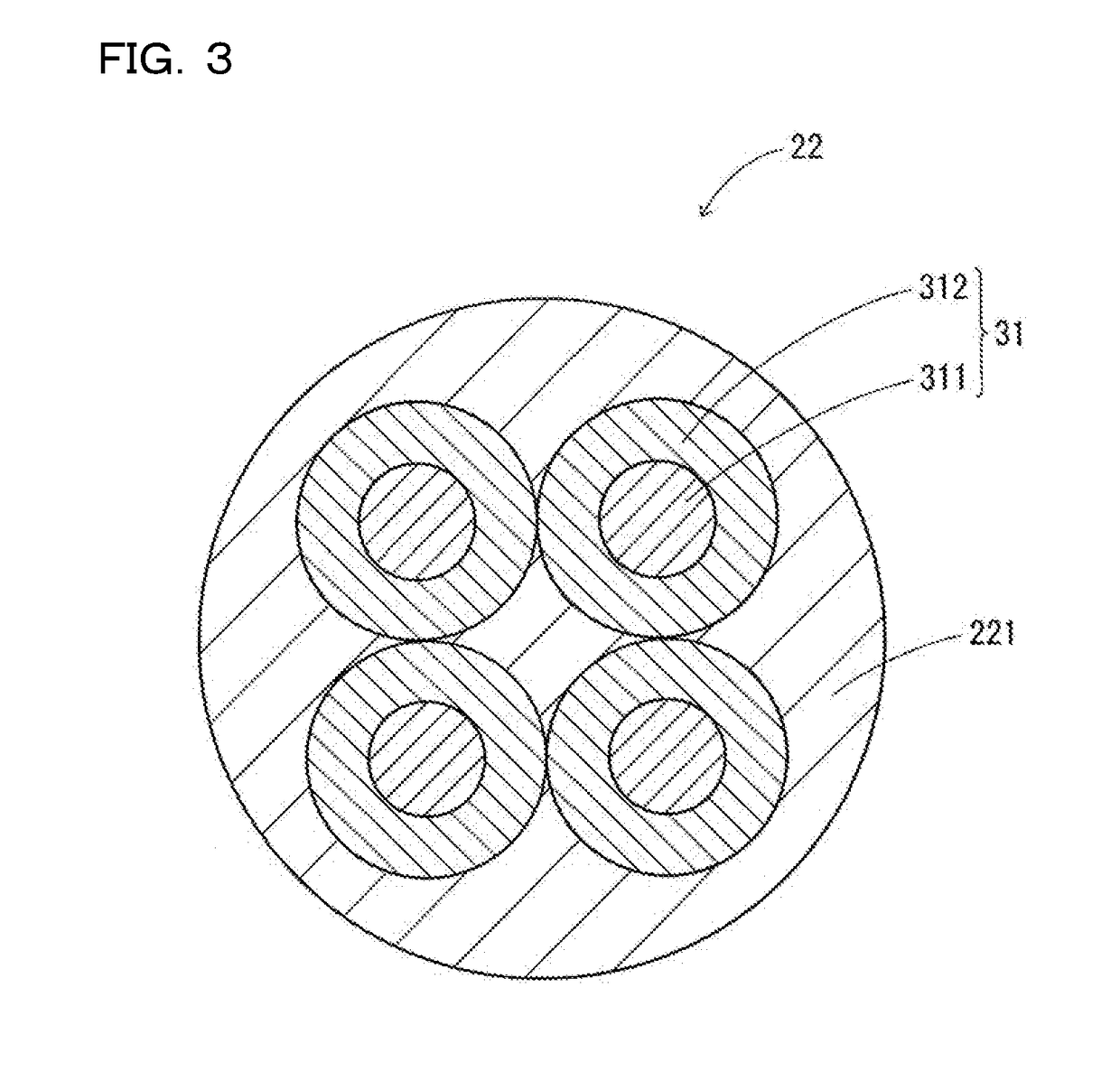
[0046]The head unit 2 and the control device 4 are connected to each other via the fiber cable 3. The fiber cable 3 includes a plurality of optical fibers 31 that respectively transmit a plurality of lights. A connector 32 is provided at one ends of the fiber cables 3. The connector 32 is detachably connected to the control device 4.

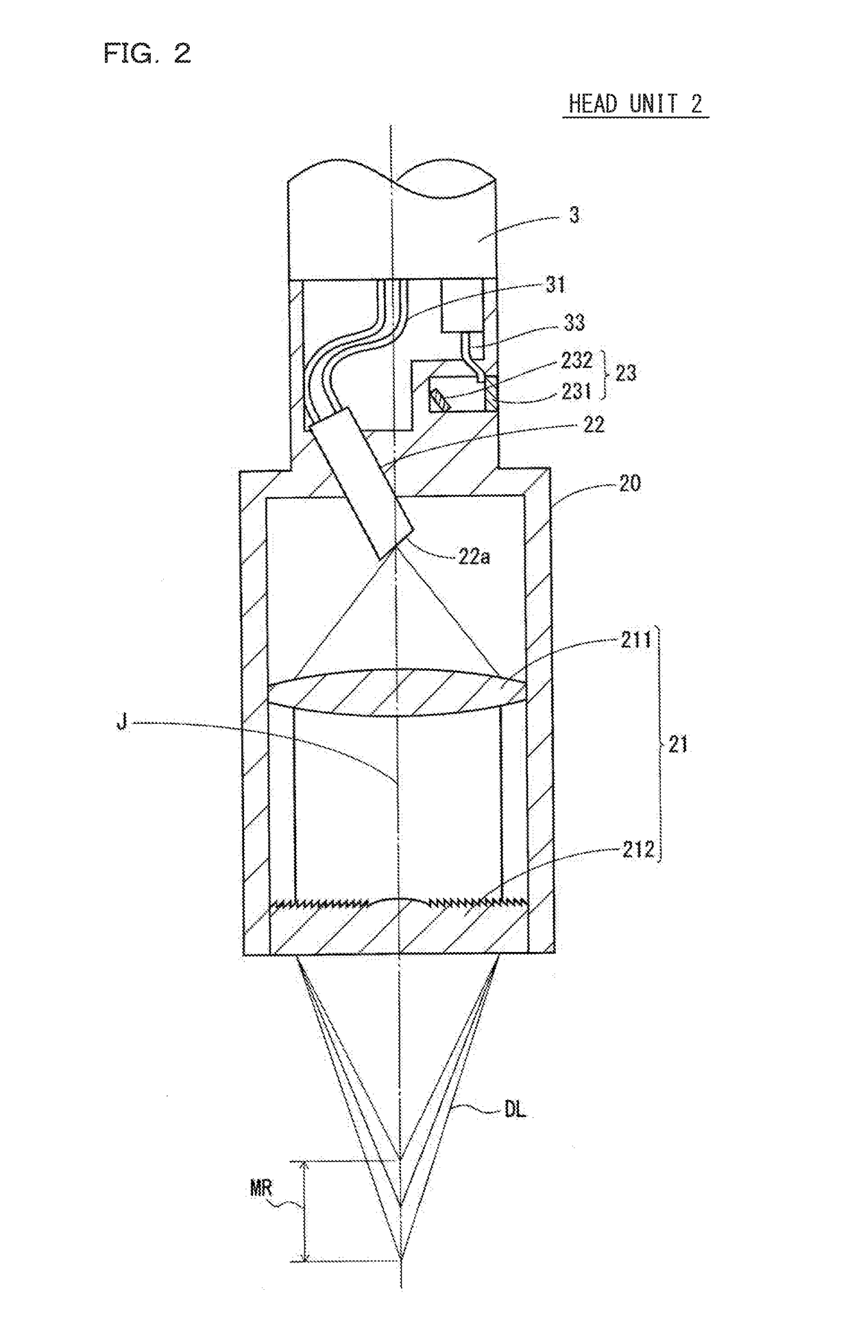
[0047]The head unit 2 is an optical unit that emits the detection lights DL toward the measurement object W. R...

second embodiment

[0106]In the first embodiment, the example is explained in which the four couplers 42 are provided to correspond to the four irradiation spots and the four detection lights DL reflected by the measurement object W are respectively independently spectrally dispersed. On the other hand, in a second embodiment, two couplers respectively combine two detection lights DL reflected by the measurement object Wand output combined lights to the spectroscope 43.

[0107]FIG. 11 is a system diagram showing a configuration example of a confocal displacement sensor 1a according to the second embodiment of the present invention. In this figure, the measurement control section 44 and the memory 45 are omitted. The confocal displacement sensor 1a is different from the confocal displacement sensor 1 shown in FIG. 1 in that a control device 4a includes two couplers 46.

[0108]The coupler 46 is an X coupler, from one end of which two optical fibers 461 and 462 extend and from the other end of which two opti...

third embodiment

[0112]In the first and second embodiments, the example is explained in which the end faces of the plurality of optical fibers 31 that transmit lights between the head unit 2 and the control device 4 are respectively caused to function as the pinholes of the confocal optical system. On the other hand, in a third embodiment, light emitted from a light source for light projection is guided to a pinhole without using an optical fiber, reflected by the measurement object W, and detection light passed through the pinhole is guided to the spectroscope 43.

[0113]FIG. 13 is a system diagram showing a configuration example of a confocal displacement sensor 1b according to the third embodiment of the present invention. In this figure, the measurement control section 44 and the memory 45 are omitted. The confocal displacement sensor 1b is configured by a light source for light projection 11, condensing lenses 12 and 14, a beam splitter 13, a pinhole member 15, the optical member 21, a lens for s...


PUM


Abstract

The confocal displacement sensor includes a light source for light projection configured to generate light having a plurality of wavelengths, a plurality of pinholes, an optical member configured to cause an axial chromatic aberration in the plurality of detection lights respectively emitted via the plurality of pinholes and converge the plurality of detection lights toward the measurement object, a spectroscope configured to respectively spectrally disperse, in the detection lights irradiated on the measurement object via the optical member, a plurality of detection lights respectively passed through the plurality of pinholes by being reflected while focusing on the measurement object and generate a plurality of light reception waveforms representing light reception intensities for each wavelength, and a measurement control section configured to statistically process the plurality of light reception waveforms and generate a representative light reception waveform from the plurality of light reception waveforms.

Description

CROSS-REFERENCE TO RELATED APPLICATIONS[0001]The present application claims foreign priority based on Japanese Patent Application No. 2017-115552, filed Jun. 13, 2017, the contents of which is incorporated herein by reference.BACKGROUND OF THE INVENTION1. Field of the Invention[0002]The present invention relates to a confocal displacement sensor and, more particularly, to improvement of a confocal displacement sensor that measures displacement of a measurement object using a confocal optical system.2. Description of Related Art[0003]A confocal displacement sensor is an optical measurement device that measures displacement of a measurement object making use of a confocal principle of stopping down received light into reflected light from an image forming surface on which an image of a light source is formed and a phenomenon of an axial chromatic aberration in which a color drift in an optical axis direction occurs in the image of the light source.[0004]The confocal displacement senso...

Claims


Application Information

Patent Timeline
Patent Type & Authority Applications(United States)
IPC IPC(8): G01B11/02G02B21/00G01B9/02
CPCG01B11/026G02B21/0064G02B21/0076G01B9/02044G01B2210/50
Inventor KUGA, SHOMAFUJIMOTO, SUKETAKATAKEI, HIDETOSUEMURA, YUSUKESAKAGUCHI, TOMIKAZU
Owner KEYENCE
Why Eureka
Eureka Blog
Learn More