Methods and systems for controlling generating units and power plants for improved performance

a technology of generating units and power plants, applied in the direction of computer control, program control, instruments, etc., can solve the problems of insufficient control systems, inefficient operation, and difficulty in achieving the goal of being particularly challenging

Active Publication Date: 2018-12-13
GENERAL ELECTRIC CO
View PDF6 Cites 17 Cited by
  • Summary
  • Abstract
  • Description
  • Claims
  • Application Information

AI Technical Summary

Benefits of technology

[0009]The present application thus describes a system including: a power plant that includes thermal generating units that are engageable according to a plurality of generating configurations for generating a plurality of output levels during a generating period, wherein, during the generating period, a generating plan schedules a selection of a generating configuration from the plurality of generating configurations and an output level from the plurality of output levels for the power plant; a hardware processor; a first user device used by a first user; a second user device that used by a second user; and a machine-readable storage medium on which is stored instructions that cause the hardware processor to execute a process related to controlling the power plant during a future generating period. The process may include the steps of: presenting on the first user device a proposed version of the generating plan for the future generating period; receiving at the first user device a user input making a first modification that modifies an aspect of the proposed version of the generating plan and, thereby, creates a bid version of the generating plan; presenting on the second user device the bid version of the generating plan so that an indicator indicates the aspect that was modified by the first modification; receiving a user input on the second user device for creating a bid for a power plant fleet for generating a fleet capacity during the future generating period, wherein the bid is based, at least in part, on the bid version of the generating plan, and wherein the power plant fleet comprises the power plant and one or more other power plants; transmitting from the second user device the bid to a predetermined destination for participating in a bidding process that determines the fleet capacity during the future generating period; receiving at the second user device a response to the bid, the response comprising an awarded fleet capacity for the future generating period; and transmitting from the second user device to the first user device an awarded plant-level capacity that is based on the awarded fleet capacity for the power plant fleet.

Problems solved by technology

Without such knowledge, such error margins typically needed to reduce the risk of overbidding the power plant during the dispatch process, which can be a costly mistake for the power plant because it may force the plant to operate inefficiently to satisfy the commitment schedule.
As will be appreciated, given the growing complexity of the modern power plant, this objective is becoming particularly challenging.
While modern power plants typical include both unit-level and plant-level control systems for addressing some of these operational issues, in many ways, these control systems are inadequate because they do not fully leverage the growing data-intensive aspects of the industrial world.
Specifically, current control systems have been unsuccessful at realizing the level of industrial optimization that the growing availability of operational data make possible, and this failure results in power plants and generating units being operated inefficiently and without maximizing economic return.
More generally, as digital and industrial environments become more fully integrated and data-intensive, many of these issues are similarly applicable to other types of industrial plants.
As with power plants, other large industrial assets or plants have become increasing complex, yet slow to fully marshal the available technology toward achieving the gains in efficiency that are possible.
This presents very difficult design and operational challenges.

Method used


Image

  • Methods and systems for controlling generating units and power plants for improved performance
  • Methods and systems for controlling generating units and power plants for improved performance
  • Methods and systems for controlling generating units and power plants for improved performance

Examples


Embodiment Construction

[0027]Example embodiments will be described more fully hereinafter with reference to the accompanying drawings, in which some, but not all embodiments are shown. Indeed, embodiments of the present disclosure may take many different forms and should not be construed as limited to the embodiments set forth herein. Like numbers may refer to like elements throughout.

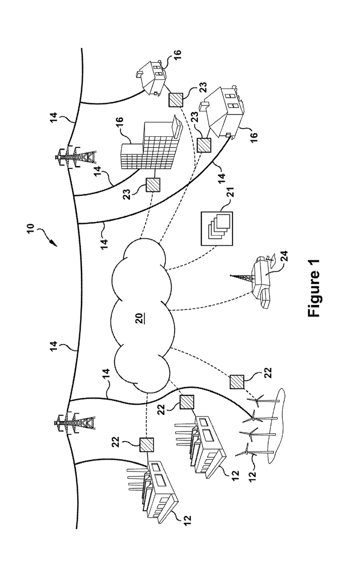
[0028]FIG. 1 illustrates a schematic representation of a power system 10 illustrating an exemplary power system environment within which embodiments of the present disclosure may operate. Power system 10 includes several power plants 12 for generating electrical power. Such power plants 10 may include wind and thermal power plants 12, as shown, but also may include other types of power plants, for example, solar power, hydroelectric, geothermal, or nuclear power plants. Within power system 10, common transmission lines 14 connect power plants 12 to one or more loads or customers 16, which, for example, may include municipali...


PUM


Abstract

A method for controlling a power plant that includes: presenting on a first user device a proposed version of the generating plan for a future generating period; receiving at the first user device a user input making a first modification to the proposed version to create a bid version of the generating plan; presenting on a second user device the bid version of the generating plan so that an indicator indicates the aspect that was modified by the first modification; receiving a user input on the second user device for creating a bid based on the bid version of the generating plan; transmitting from the second user device the bid; receiving at the second user device a response comprising an awarded fleet capacity; and transmitting from the second user device to the first user device an awarded plant-level capacity based on the awarded fleet capacity.

Description

CROSS-REFERENCE TO RELATED APPLICATIONS[0001]This application claims priority to U.S. Provisional Patent Application No. 62 / 518446 entitled “System and Method Related to Plant Manager and Trader Optimization Interface” filed on Jun. 12, 2017; which provisional application is incorporated herein by reference in its entirety; this application claims the benefit of the provisional's filing date under 35 U.S.C. 119(e).BACKGROUND OF THE INVENTION[0002]The present application relates generally to the control of industrial machines and assets. More specifically, but not by way of limitation, the present application relates to controlling industrial machines and assets, particularly those related to power generation industry, via controllers implementing analytics, processes, and graphical screen displays that improve aspects of operational performance.[0003]For example, in regard to the power generation industry, the marketplace typically includes geographically defined power systems withi...

Claims


Application Information

Patent Timeline
Patent Type & Authority Applications(United States)
IPC IPC(8): G05B19/042
CPCG05B19/042G05B2219/2639G06Q50/06G06Q50/04Y02P90/30Y04S10/50
Inventor HALABIEH, ABDUL
Owner GENERAL ELECTRIC CO
Why Eureka
Try Eureka