

Solar panel comprising notably a structure and at least two photovoltaic cells
- Summary
- Abstract
- Description
- Claims
- Application Information
AI Technical Summary
Benefits of technology
Problems solved by technology
Method used
Image

Examples
first embodiment
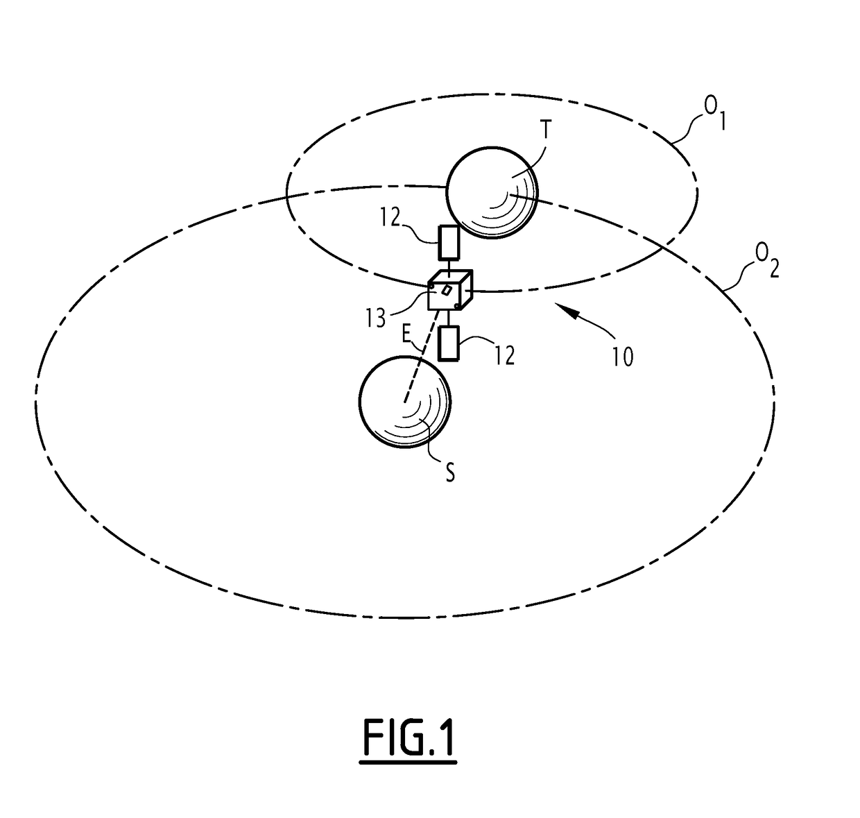
[0080]According to the invention, the cells 16A and 16B are arranged such that the shade generated by the barrier 18A when the direction perpendicular P to the panel surface 19 moves away from the lighting direction E of the maximum separation angle αmax, is substantially outside each of the two cells 30A, 30B.
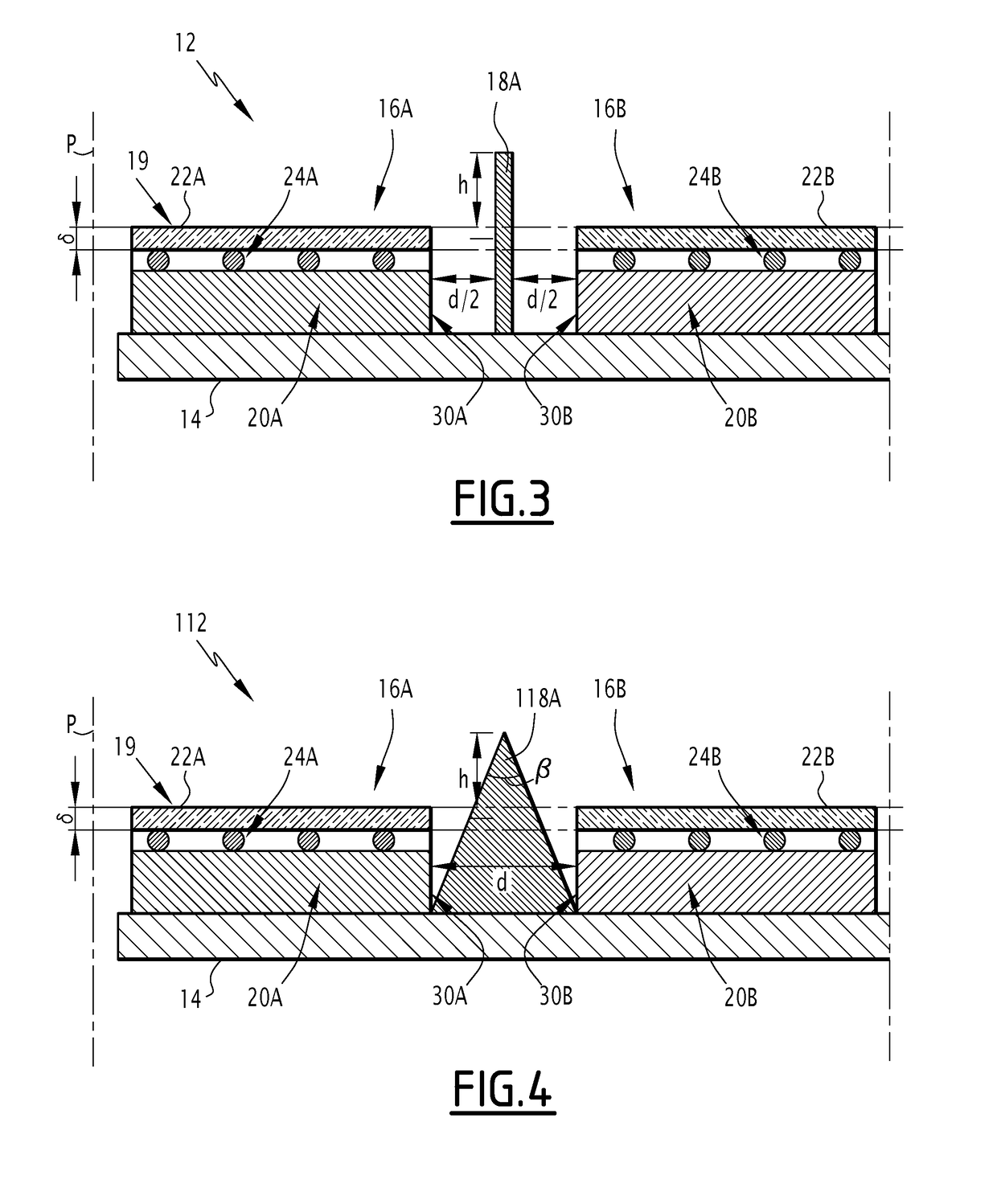
[0081]Thus, according to this embodiment, the distance d between the lateral contact faces 30A, 30B of the cells 16A, 16B is for example comprised between 6 mm and 12 mm, preferably between 8 mm and 10 mm, and advantageously equal to about 9 mm.
[0082]The barrier 18A is therefore separated from each of the lateral contact faces 30A, 30B by about 4.5 mm.
[0083]One can then see that the present invention has a certain number of advantages.
[0084]First, it has been demonstrated that when the shortest path between conductive components of the adjacent photovoltaic cells increases, the risk of establishment of an electric arc between these components is greatly decreased.
[0085]Thus, a...
second embodiment
[0090]A solar panel 112 according to the invention is illustrated in FIG. 4.
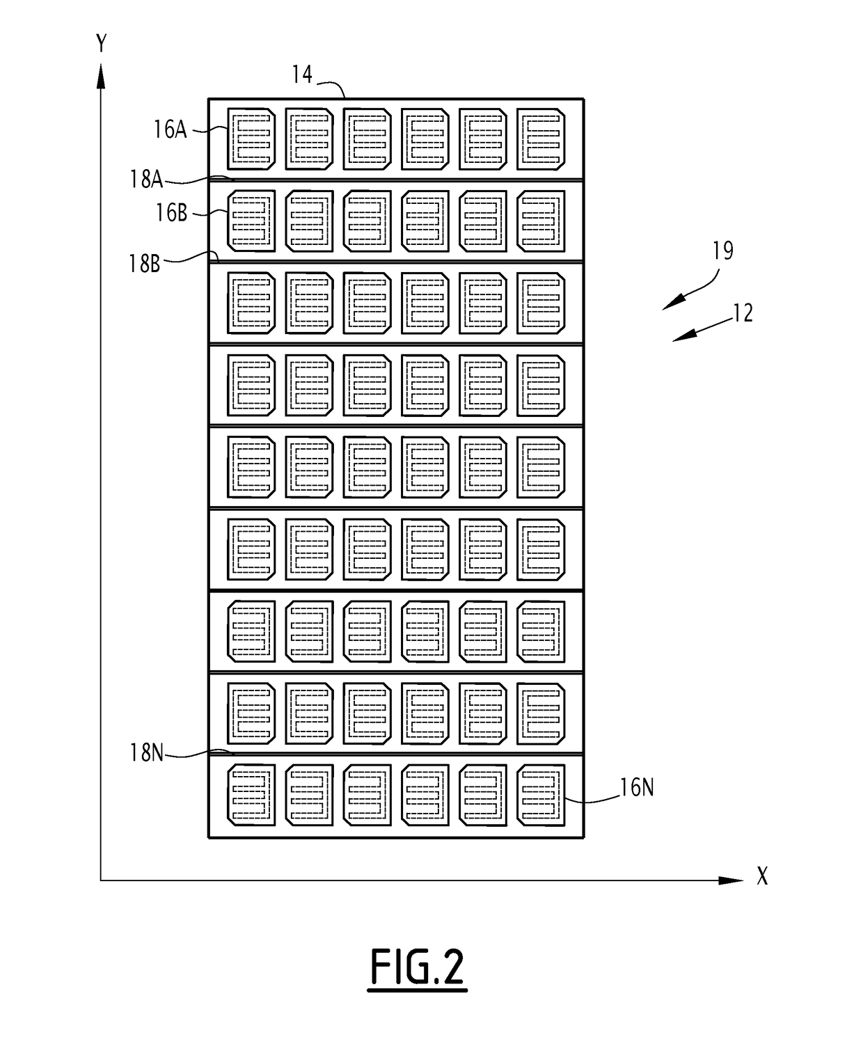
[0091]The solar panel 112 is similar to the solar panel 12 previously described and in particular includes a structure 14 and photovoltaic cells 16A to 16N substantially identical to those previously described.
[0092]The solar panel 112 further includes a plurality of barriers 118A to 118N that differ from the barriers 18A to 18N previously described only by their shape in cross-section.
[0093]Thus, as illustrated in FIG. 4 in connection with the barrier 118A, each barrier 118A to 118N has a cross-section in the shape of an isosceles triangle.
[0094]The length of the base of this triangle is equal to the value of the distance d previously mentioned, the triangle protruding relative to the panel surface 19 by the same value h previously mentioned.
[0095]The angle β of the triangle regarding the base is equal to about two maximal separating angles Δmax.
[0096]Thus, like in the previous case, the barriers 118A to 11...
third embodiment
[0097]A solar panel 212 according to the invention is illustrated in FIG. 5.
[0098]The solar panel 212 is similar to the solar panel 112 previously described and in particular includes a structure 14 and photovoltaic cells 16A to 16N substantially identical to those previously described.
[0099]The solar panel 212 further includes a plurality of barriers 218A to 218N that differ from the barriers 118A to 118N previously described in that each barrier 218A to 218N assumes the form of a concentrator.
[0100]Thus, as illustrated in FIG. 5 in connection with the barrier 218A, each barrier 218A to 218N has a cross-section in the shape of a curved isosceles triangle with a straight base.
[0101]The length of the base of this triangle is equal to the value of the distance d previously mentioned, the triangle protruding relative to the panel surface 19 by the same value h previously mentioned.
[0102]The angle β of the triangle regarding the base is equal to about two maximal separating angles Δmax....
PUM
 Abstract
Description
Claims
Application Information