
Apparatus and method for estimating position of the center of gravity of robot

a technology of robot center and approximation method, which is applied in the direction of programmed manipulators, instruments, programme control, etc., can solve the problem that the estimation technique cannot be used in robots which are horizontal 4

Active Publication Date: 2018-12-20
DENSO WAVE INC
View PDF12 Cites 4 Cited by
  • Summary
  • Abstract
  • Description
  • Claims
  • Application Information

AI Technical Summary

Benefits of technology

This patent text describes a method and apparatus to estimate the position of the center of gravity of a load mounted on the tip of an arm of a horizontal 4-axis configuration robot. This helps to control the robot arm in a more reliable and precise manner, even if the loads being loaded to the robot have indefinite shapes or irregular densities. The method uses acceleration measurements along with pre-defined angles to calculate the position of the center of gravity. The configuration of the robot arm and the placement of the acceleration acquiring units facilitate the accurate positioning of the center of gravity, while minimizing vibration or shaking motions that could affect the load.

Problems solved by technology

This foregoing estimation technique proposed by Japanese Patent No. 5327722 is based on the use of such a changing technique using the fifth axis, but this estimation technique cannot be used in robots which are horizontal 4-axis configuration robots, due to the fact that the state where a force of gravity acts on a workpiece cannot be changed.

Method used


Image

  • Apparatus and method for estimating position of the center of gravity of robot
  • Apparatus and method for estimating position of the center of gravity of robot
  • Apparatus and method for estimating position of the center of gravity of robot

Examples


Embodiment Construction

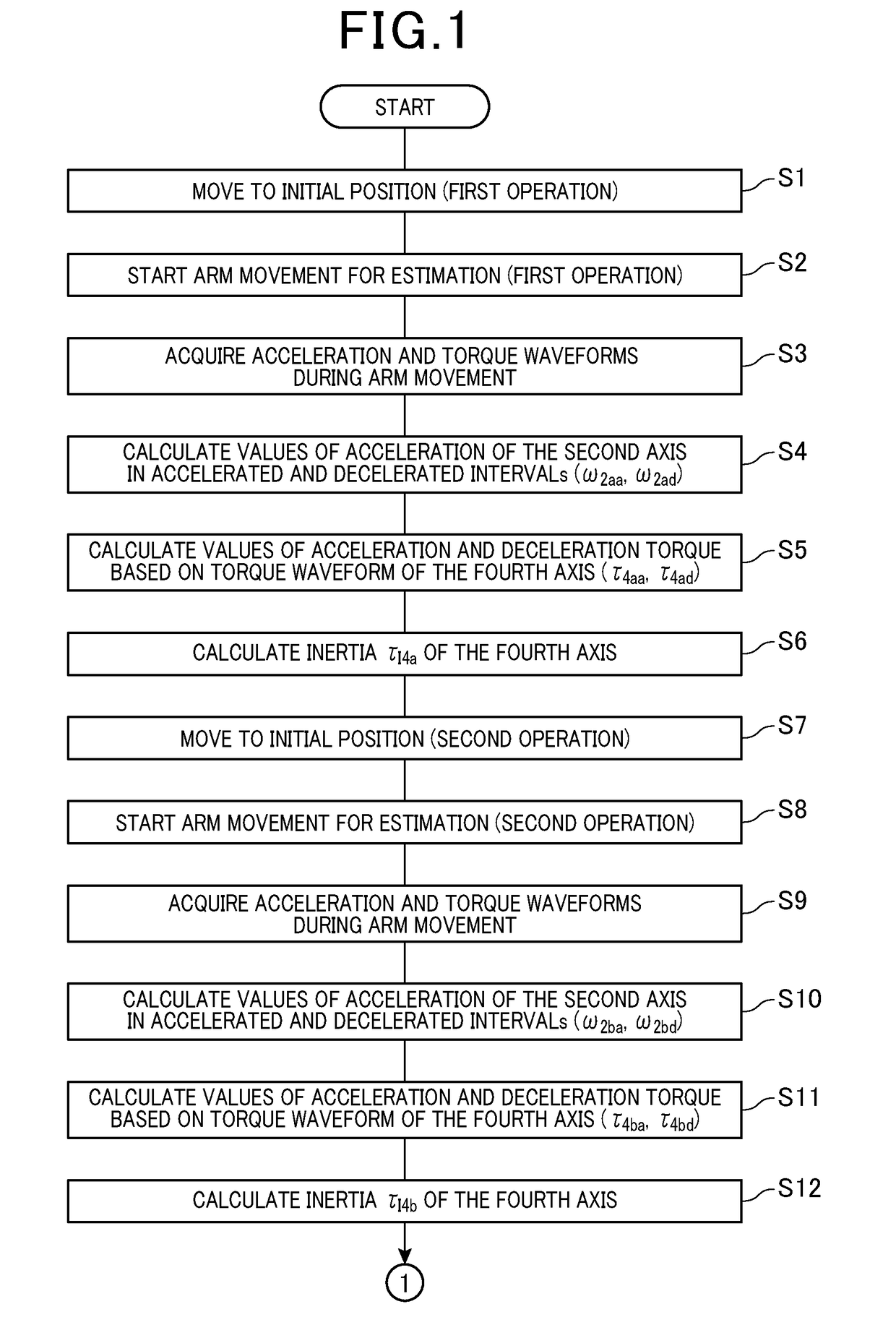
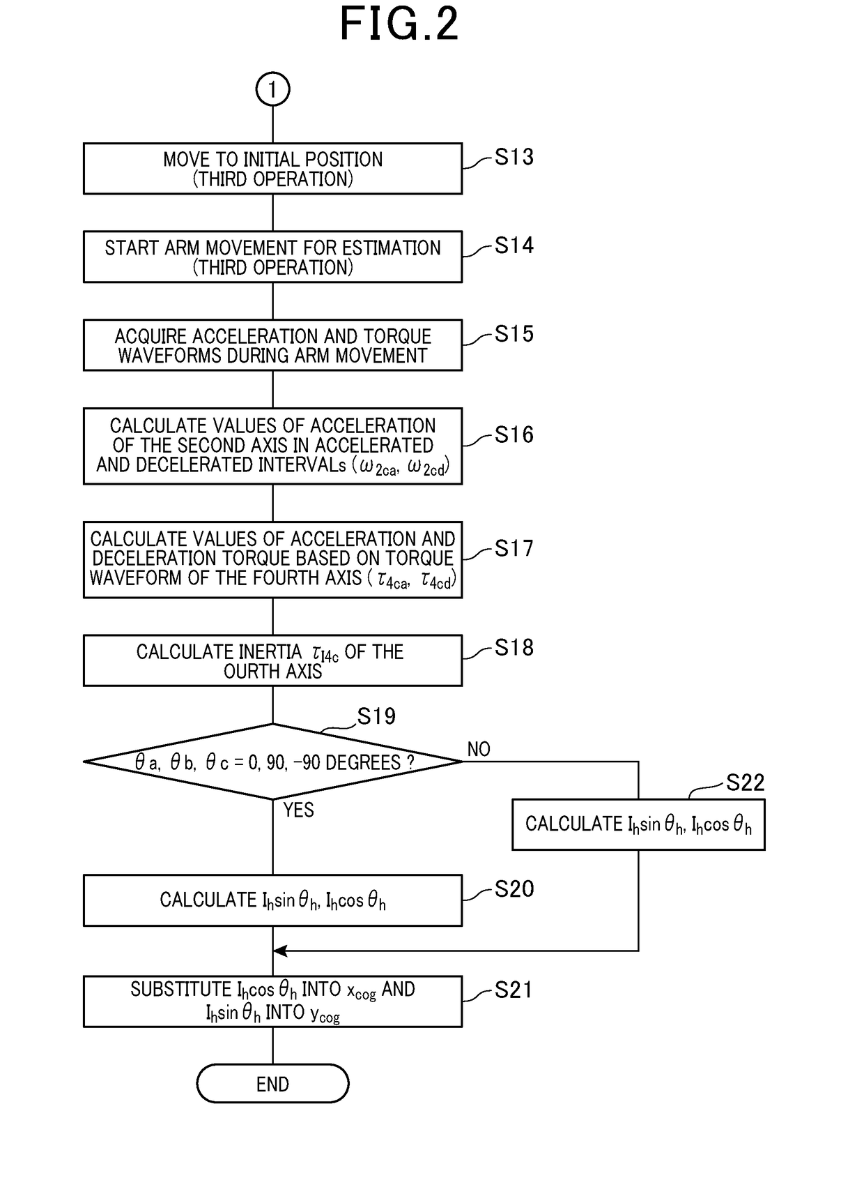
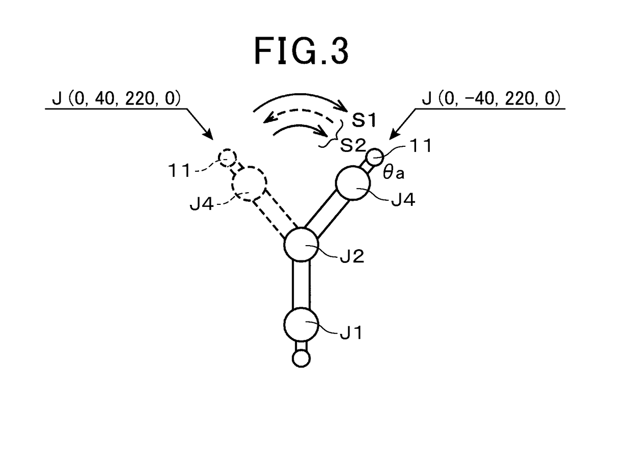
[0025]Hereinafter, with reference to FIGS. 1 to 10, a preferred embodiment will now be described according to an apparatus and method for estimating the position of the center of gravity of a load amounted on the arm end of an industrial robot.

[0026]First of all, by using FIG. 9, a whole system will be described. FIG. 9 shows a system configuration of one of ordinarily used industrial robots, in which a robot system 1 is provided. This robot system 1 is provided with an industrial robot 2, a controller 3 which controls motions of the robot 2, and a teaching pendant 4 communicably connected to the controller 3. The controller 3 can serve as a control apparatus and an estimation apparatus for estimating a center of gravity of a load attached to the robot 2.

[0027]The robot 2 is configured, for example, as a 4-axis horizontal multi-articulated robot, and is equipped with a base 5 fixedly mounted on an installation surface of, for example, a floor, a first arm 6 rotatably built on the ba...


PUM


Abstract

A position of gravity of center of a load loaded to an industrial load is estimated. The robot has a robot arm driven horizontally. The robot arm includes first to fourth axis. Acceleration generated at the second axis during accelerated and decelerated intervals of each of three operation periods. In each operation period, the second axis is driven to move the robot arm from one initial position to one first estimating position and returns it from the estimating position to the initial position. During each operation period, the load is given a known mass, the fourth axis is positioned at a preset angle, and the first, third and fourth axes are the same in positions between the initial and estimating positions. The fourth-axis position is changed to different angles for every operation period. Based on calculated acceleration and known factors of the robot and load, the position is estimated.

Description

CROSS-REFERENCE TO RELATED APPLICATION[0001]This application is based on and claims the benefit of priorities from earlier Japanese Patent Application No. 2017-117669 filed Jun. 15, 2017, the description of which is incorporated herein by reference.BACKGROUNDTechnical Field[0002]The present invention relates to an apparatus and method for estimating the position of the center of gravity of a load amounted on the arm end of a robot, and in particular, to the apparatus and method which can preferably applied to an industrial robot of a horizontal 4-axis configuration.Related Art[0003]There is known a conventional technique for estimating the position of the center of gravity of a workpiece held as a load by the end of an arm of a vertical 6-axis robot arm. This technique is for example proposed by Japanese Patent No. 5327722.[0004]In the configuration of the vertical 6-axis robot arm, the fifth axis can be activated to change a state where a force of gravity acts on a workpiece. It is...

Claims


Application Information

Patent Timeline
Patent Type & Authority Applications(United States)
IPC IPC(8): B25J9/16G05B19/402
CPCB25J9/1607G05B19/402B25J9/1694G05B2219/35124G05B2219/40269B25J9/1602B25J13/088B25J9/1638
Inventor TAKAMURA, NORITAKA
Owner DENSO WAVE INC
Learn More