Apparatus and Method for Planarizing Multiple Shadow Masks on a Common Carrier Frame

a technology of shadow masks and masks, applied in the direction of instruments, vacuum evaporation coatings, coatings, etc., can solve the problems of material being vapor deposited in such gaps, becoming increasingly difficult to maintain accurate dimensional stability,

Inactive Publication Date: 2018-12-20
ADVANTECH GLOBAL LTD
View PDF5 Cites 6 Cited by
  • Summary
  • Abstract
  • Description
  • Claims
  • Application Information

AI Technical Summary

Problems solved by technology

A problem, however, with forming increasingly larger area sized shadow masks is in avoiding run-on errors in positioning of openings across the dimensions of the shadow mask.
Stated differently, a problem with forming increasingly larger area sized shadow masks is that it becomes increasingly more difficult to maintain accurate dimensional stability between openings used for depositing patterns of material on a substrate across the dimensions of the shadow mask.
A challenge with the approach disclosed in the PCT application is in ensuring that each individual shadow mask of the number of shadow masks is properly oriented on the carrier frame, which may not have a flat or planar surface on which to mount the shadow masks.
Absent the carrier frame having such flat or planar surface, there exists the possibility that contacting surfaces of each shadow mask and a substrate on which a deposition event is to occur are not parallel, or not substantially parallel, whereupon one or more unintentional gaps form between said surfaces whereupon, during a deposition event via apertures in the shadow mask, material being vapor deposited can undesirably enter such gaps and be deposited on one or both of the surfaces of the shadow mask and the substrate defining said gaps, an undesirable condition.

Method used


Image

  • Apparatus and Method for Planarizing Multiple Shadow Masks on a Common Carrier Frame
  • Apparatus and Method for Planarizing Multiple Shadow Masks on a Common Carrier Frame
  • Apparatus and Method for Planarizing Multiple Shadow Masks on a Common Carrier Frame

Examples


Embodiment Construction

[0049]Various non-limiting examples will now be described with reference to the accompanying figures where like reference numbers correspond to like or functionally equivalent elements.

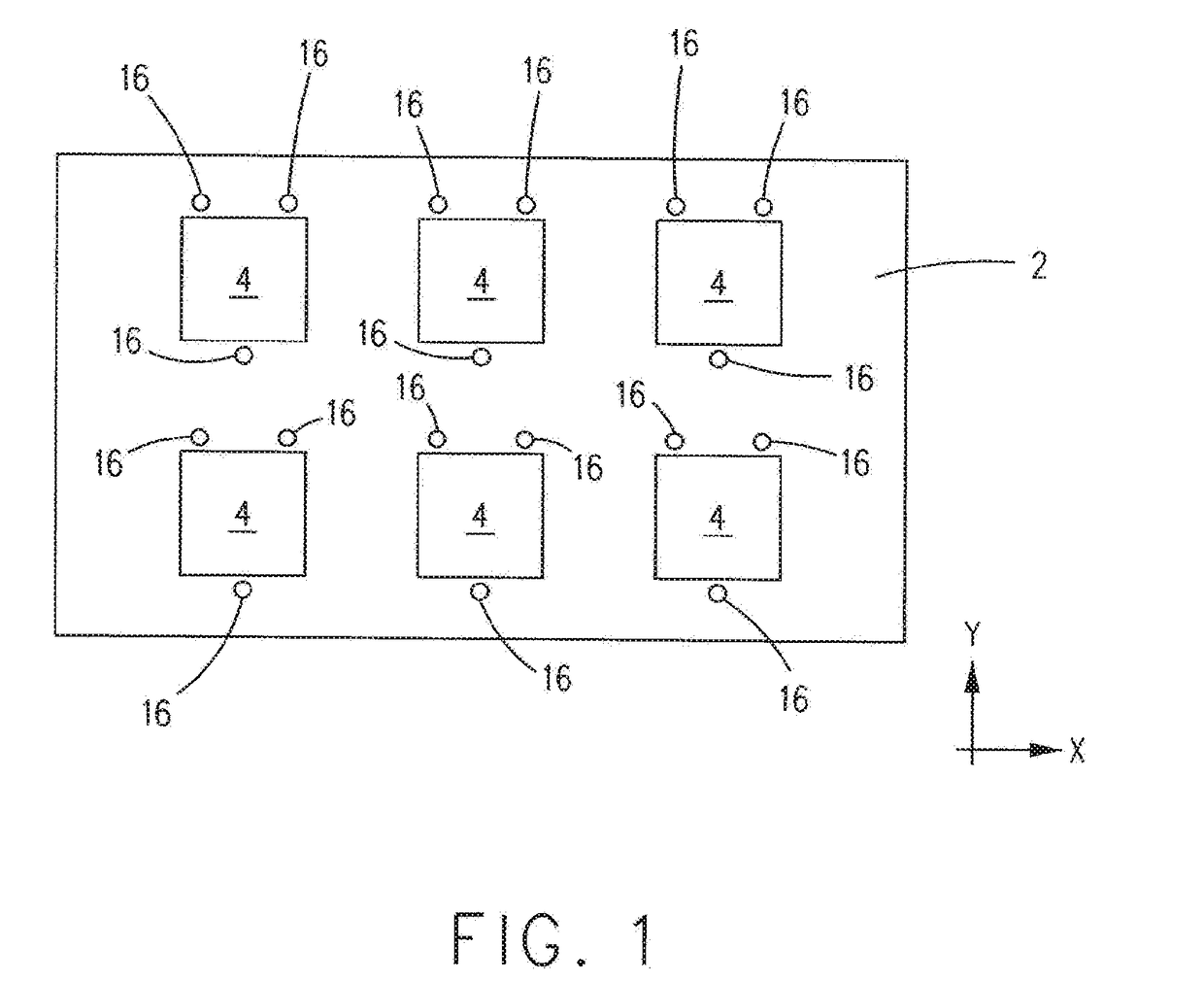
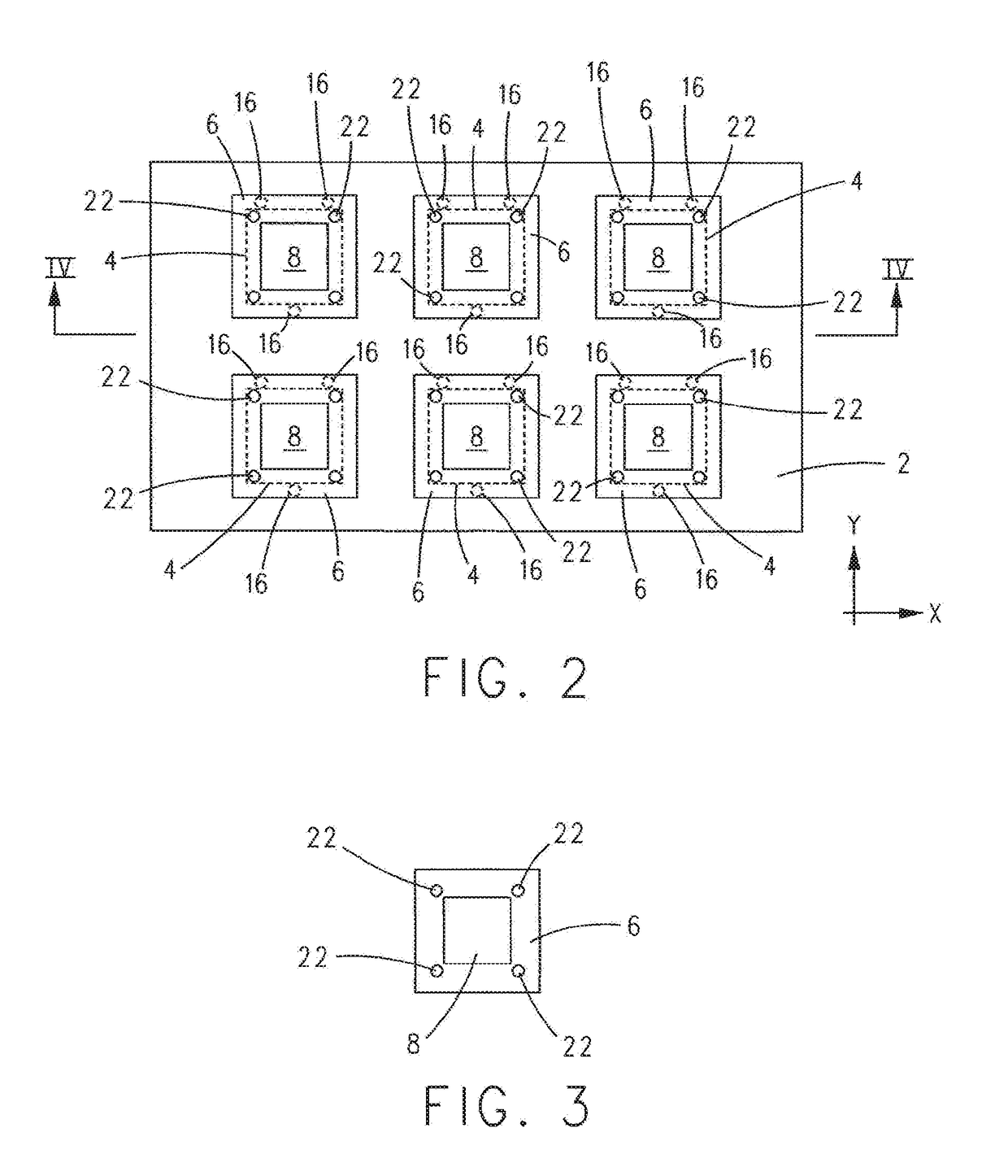
[0050]The various example multi-mask alignment systems described herein enable construction of an effectively larger area shadow mask out of a number of smaller area shadow masks. By constructing the effectively larger area shadow mask out of smaller area shadow masks, it is possible to maintain greater geometrical precision of the holes and apertures in the smaller shadow masks over a larger area, e.g., over an area larger than each smaller shadow mask alone. Since each small shadow mask is independent of the other small shadow masks, it is also possible to properly size the holes and apertures of each small shadow mask without affecting the dimensions of the other small shadow mask.

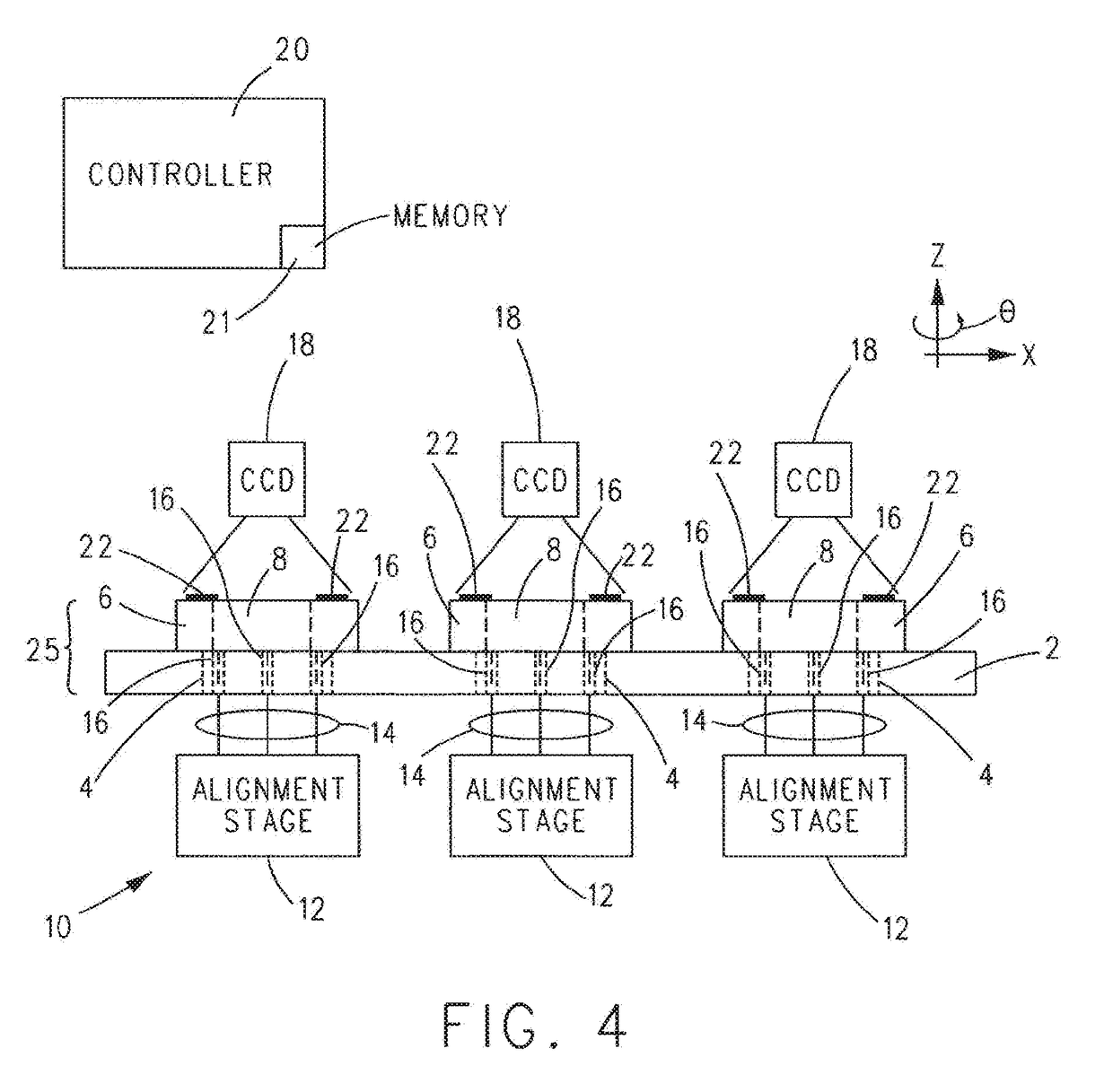
[0051]The various example multi-mask alignment systems described herein provide for aligning a number of small area sha...


PUM

PropertyMeasurementUnit
lengthaaaaaaaaaa
areaaaaaaaaaaa
dimensional stabilityaaaaaaaaaa

Abstract

In an apparatus and method for multi mask alignment, a carrier is provided that includes apertures therethrough. For each aperture, a combination frame and shadow mask that includes alignment features is positioned on spacers supported by the carrier with the shadow mask of the combination in coarse alignment with the aperture. Next, each combination frame and shadow mask is moved to a position spaced from the spacers whereupon the alignment system, under the control of a controller, individually aligns each combination frame and shadow mask to align the alignment features of the combination with reference alignment features associated with the combination. Each combination frame and shadow mask is then returned to a position on the spacers whereafter each combination frame and shadow mask is secured to the carrier. In an example, all of the combination frames and shadow masks can be aligned simultaneously.

Description

CROSS REFERENCE TO RELATED APPLICATIONS[0001]This application claims the benefit of U.S. Provisional Patent Application No. 62 / 290,096, filed Feb. 2, 2016, the contents of which are incorporated herein in its entirety by reference.BACKGROUND OF THE INVENTIONField of the Invention[0002]The present invention relates to planarizing each instance of a combination frame and shadow mask mounted on a carrier frame as well as planarizing a number of combination frames and shadow masks mounted on the carrier frame with respect to each other.Description of Related Art[0003]In the field of shadow mask vapor deposition, there is a trend to utilize increasingly larger area shadow masks that include one or more openings corresponding to a desired pattern of material to be deposited on a substrate from a deposition source. A problem, however, with forming increasingly larger area sized shadow masks is in avoiding run-on errors in positioning of openings across the dimensions of the shadow mask. St...

Claims


Application Information

Patent Timeline
Patent Type & Authority Applications(United States)
IPC IPC(8): C23C14/04G01B11/27C23C14/54
CPCC23C14/042G01B11/272C23C14/54C23C16/042C23C14/04C23C16/04H10K71/166
Inventor BUCCI, BRIAN ARTHURMONTO, DAVID N.TUNG, SHEN-CHIH
Owner ADVANTECH GLOBAL LTD
Why Eureka
Try Eureka