Polarized type viewing angle control element, polarized type viewing angle control display module, and polarized type viewing angle control light source module
a technology of polarized type and control element, which is applied in the direction of optics, polarising elements, instruments, etc., can solve the problems of deteriorating display quality, lcf not only has high price and large thickness, but also reduces the overall luminance of the display device by 30%, so as to avoid significant luminance reduction
- Summary
- Abstract
- Description
- Claims
- Application Information
AI Technical Summary
Benefits of technology
Problems solved by technology
Method used
Image
Examples
second embodiment
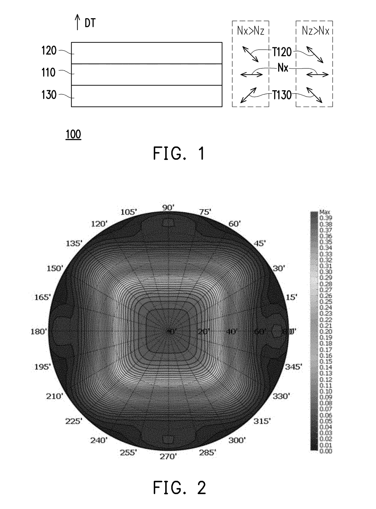
[0047]Referring to FIG. 11, a polarized type viewing angle control display module 20 provided in the invention is similar to the polarized type viewing angle control display module 10 depicted in FIG. 10, wherein identical elements are indicated by identical reference numerals and will not be further described hereinafter.
[0048]Main differences between the polarized type viewing angle control display module 20 and the polarized type viewing angle control display module 10 depicted in FIG. 10 are described as follows. In the polarized type viewing angle control display module 20, the polarized type viewing angle control element 100 is located between the display module DM and the light source module LM, and a transmission axis (e.g., the transmission axis T120) of a polarizer (e.g., the polarizer 120) proximate to the display module polarizer P in the polarized type viewing angle control element 100 is parallel to the transmission axis TP of the display module polarizer P. The displa...
third embodiment
[0049]Referring to FIG. 12, a polarized type viewing angle control display module 30 provided in the invention is similar to the polarized type viewing angle control display module 10 depicted in FIG. 10, wherein identical elements are indicated by identical reference numerals and will not be further described hereinafter.
[0050]Main differences between the polarized type viewing angle control display module 30 and the polarized type viewing angle control display module 10 depicted in FIG. 10 are described as follows. In the polarized type viewing angle control display module 30, a transmission axis (e.g., the transmission axis T130) of a polarizer (e.g., the polarizer 130) proximate to the display module polarizer P in the polarized type viewing angle control element 100 is not parallel to the transmission axis TP of the display module polarizer P. In addition, the polarized type viewing angle control display module 30 further includes a half-wave plate 170. The half-wave plate 170 ...
fourth embodiment
[0051]Referring to FIG. 13, a polarized type viewing angle control display module 40 provided in the invention is similar to the polarized type viewing angle control display module 20 depicted in FIG. 11, wherein identical elements are indicated by identical reference numerals and will not be further described hereinafter.
[0052]Main differences between the polarized type viewing angle control display module 40 and the polarized type viewing angle control display module 20 depicted in FIG. 11 are described as follows. In the polarized type viewing angle control display module 40, a transmission axis (e.g., the transmission axis T120) of a polarizer (e.g., the polarizer 120) proximate to the display module polarizer P in the polarized type viewing angle control element 100 is not parallel to the transmission axis TP of the display module polarizer P. In addition, the polarized type viewing angle control display module 40 further includes a half-wave plate 170. The half-wave plate 170 ...
PUM
| Property | Measurement | Unit |
|---|---|---|
| 2θ | aaaaa | aaaaa |
| angle | aaaaa | aaaaa |
| refractive indices | aaaaa | aaaaa |
Abstract
Description
Claims
Application Information
 - R&D
- Intellectual Property
- Life Sciences
- Materials
- Tech Scout
- Unparalleled Data Quality
- Higher Quality Content
- 60% Fewer Hallucinations
Browse by: Latest US Patents, China's latest patents, Technical Efficacy Thesaurus, Application Domain, Technology Topic, Popular Technical Reports.
© 2025 PatSnap. All rights reserved.Legal|Privacy policy|Modern Slavery Act Transparency Statement|Sitemap|About US| Contact US: help@patsnap.com


