
Motor and vehicle including same

a technology applied in the field of motors and vehicles, can solve the problems of increasing the amount of ripple components of torques, and achieve the effect of maximizing torque and minimizing current rippl

Active Publication Date: 2018-12-20
KOA AUTOMOTIVE CO LTD
View PDF11 Cites 0 Cited by
  • Summary
  • Abstract
  • Description
  • Claims
  • Application Information

AI Technical Summary

Benefits of technology

The patent text describes a motor design that reduces current ripple and maximizes torque. This is achieved by placing brushes at a specific angle in relation to the magnets and slots in the rotor. The technical effect is a more efficient and effective motor design.

Problems solved by technology

When the amount of the ripple component of the current is increased, there is a problem in that an amount of a ripple component of a torque is also increased.

Method used


Image

  • Motor and vehicle including same
  • Motor and vehicle including same
  • Motor and vehicle including same

Examples


Embodiment Construction

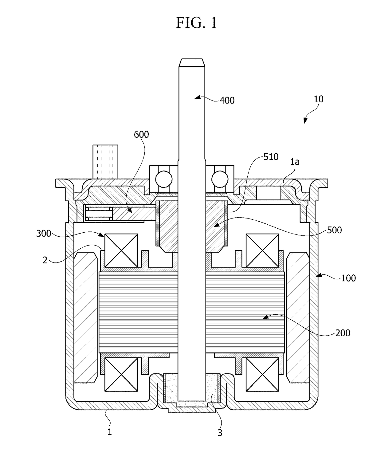
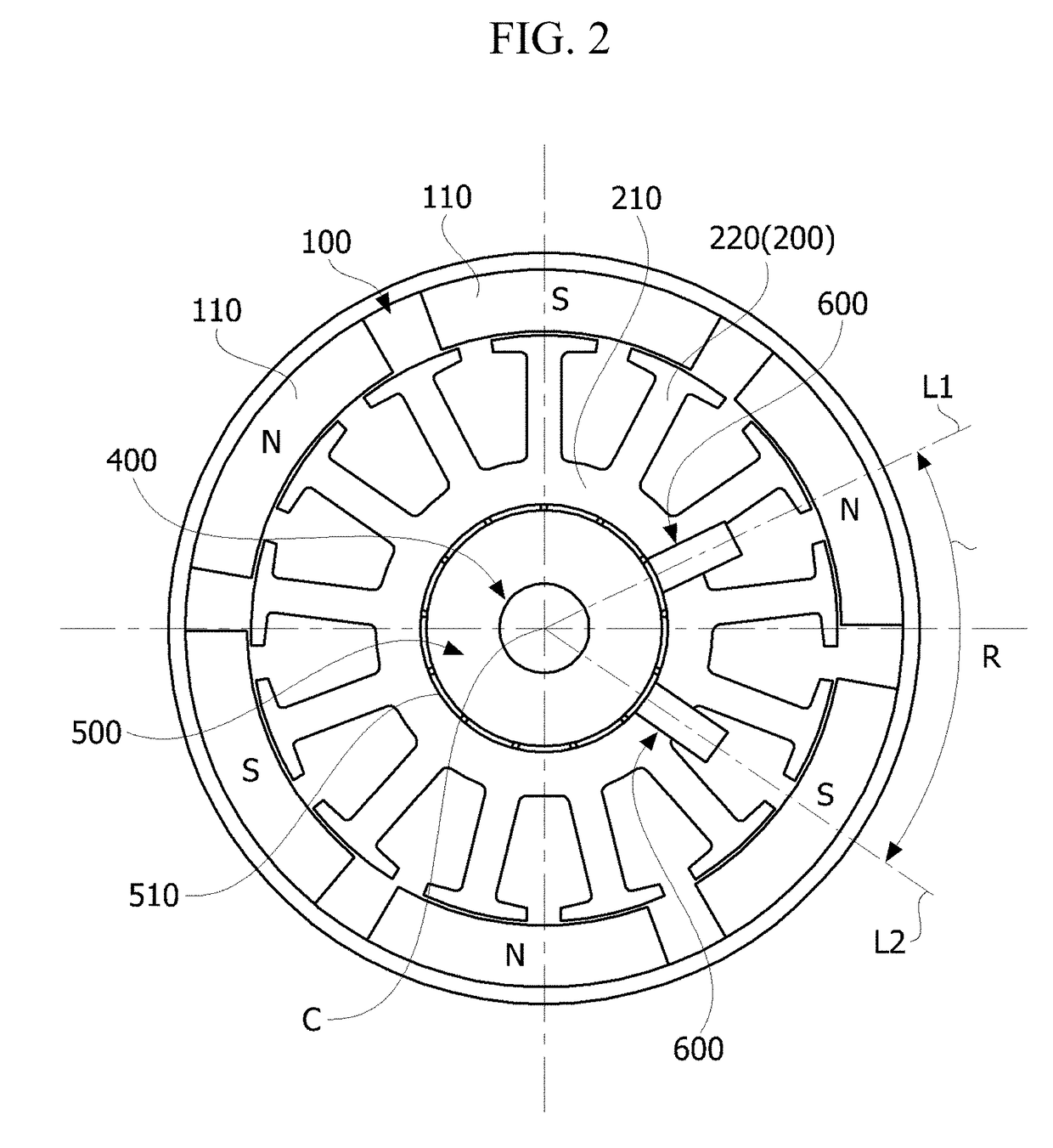
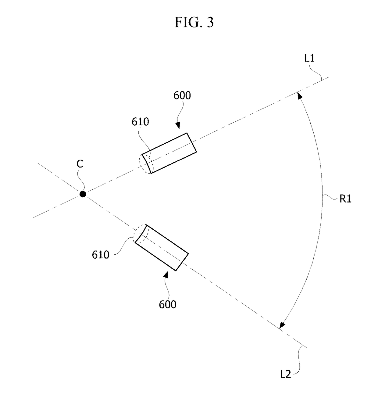
[0022]Hereinafter, exemplary embodiments of the present invention will be described in detail with reference to the accompanying drawings. Purposes, specific advantages, and novel features of the present invention will be clear from the exemplary embodiments and the following detailed descriptions in connection with the accompanying drawings. Terms and words used in this specification and claims are not to be interpreted as limited to commonly used meanings or meanings in dictionaries and should be interpreted with meanings and concepts which are consistent with the technological scope of the present invention based on the principle that the inventor has appropriately defined concepts of terms in order to describe the present invention in the best way. In addition, in descriptions of the present invention, when it is determined that detailed descriptions of related well-known functions unnecessarily obscure the gist of the present invention, the detailed descriptions will be omitted...


PUM


Abstract

The present invention provides a stator including magnets having six poles; a rotor disposed inside the stator and including thirteen slots; a coil wound around the slot; a rotary shaft coupled to the rotor; a commutator coupled to the rotary shaft and connected to the coil; and a plurality of brushes disposed to be pressed against the commutator and located to have an angular interval of 63° to 66° in the circumferential direction of the rotary shaft, thereby providing advantageous effects in that a current ripple is minimized and a torque is maximized.

Description

TECHNICAL FIELD[0001]The present invention relates to a motor and a vehicle including the same.BACKGROUND ART[0002]A motor includes a rotary shaft formed to be rotatable, a rotor coupled to the rotary shaft, and stators fixed inside a housing. The stators are installed along a circumference of the rotor and spaced a distance from each other. Rotation of the rotor is induced due to an electrical interaction in the motor. In a case in which coils are wound around the rotor, a commutator and a brush are provided for supplying a current to the coils wound around the rotating rotor.[0003]Generally, the commutator is coupled to the rotary shaft to be rotated while being coupled to the coils, and brushes are coupled to the housing and disposed to be in contact with the commutator. Here, the brushes are in contact with the commutator to supply a current to the commutator.[0004]Meanwhile, the stator may include magnets, and the magnets may have six poles. In addition, thirteen slots of a rot...

Claims


Application Information

Patent Timeline
Patent Type & Authority Applications(United States)
IPC IPC(8): H02K13/10H01R39/18
CPCH02K13/10H01R39/18H02K2213/03H02K1/24H02K1/17
Inventor KIM, JAE YOUNGKIM, HONG HYOUN
Owner KOA AUTOMOTIVE CO LTD
Features
  • Generate Ideas
  • Intellectual Property
  • Life Sciences
  • Materials
  • Tech Scout
  • Unparalleled Data Quality
  • Higher Quality Content
  • 60% Fewer Hallucinations
Learn More