
Light control system and method thereof

Active Publication Date: 2018-12-20
COOLER MASTER TECH
View PDF7 Cites 2 Cited by
  • Summary
  • Abstract
  • Description
  • Claims
  • Application Information

AI Technical Summary

Benefits of technology

The present disclosure proposes a light control system and method that integrates various types of light devices connecting to the personal computer. This results in consistent and coordinated illumination effects with the color of the display screen, improving the visual aesthetic around the computer and enhancing the user's immersion while playing the game. The light control system can be used in various application fields such as mood lighting, home lighting, and stage lighting. The configuration file for controlling the lighting can be stored in the microcontroller, computer, or cloud server, improving the portability of the light control system. Overall, the light control system described in the present disclosure improves the user's entertainment experience.

Problems solved by technology

Therefore, if the user assembles a custom-built computer by himself, the user often faces an embarrassing situation, the color lights emitted by the light devices at each position lacks coordination or consistency, and cannot achieve the extension effect of the situational light of the current display screen.
On the contrary, it may become a burden of visual fatigue, resulting in a poor user experience.
Although the gaming computer suit can use the motherboard or the chassis with the same specification of the light control interface, this type of product is often expensive.
Once one of the light device is damaged, the lighting component that user replaces by himself usually cannot work with the original lighting system, thus causing a lot of inconveniences.
As described above, currently there is no light control system that can be applied to a variety of light devices.

Method used


Image

  • Light control system and method thereof
  • Light control system and method thereof
  • Light control system and method thereof

Examples


Embodiment Construction

[0026]In the following detailed description, for purposes of explanation, numerous specific details are set forth in order to provide a thorough understanding of the disclosed embodiments. It will be apparent, however, that one or more embodiments may be practiced without these specific details. In other instances, well-known structures and devices are schematically shown in order to simplify the drawings.

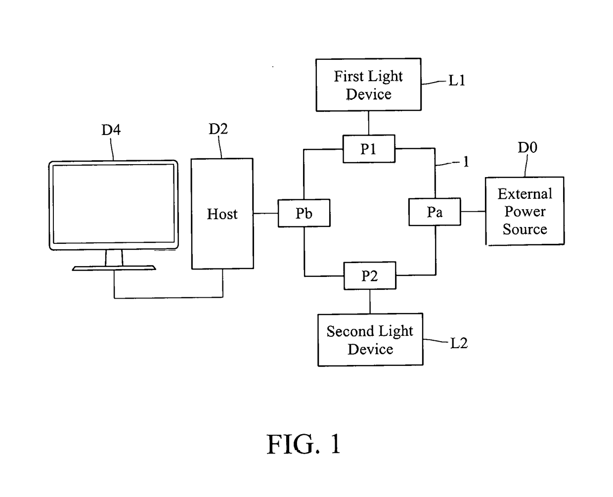
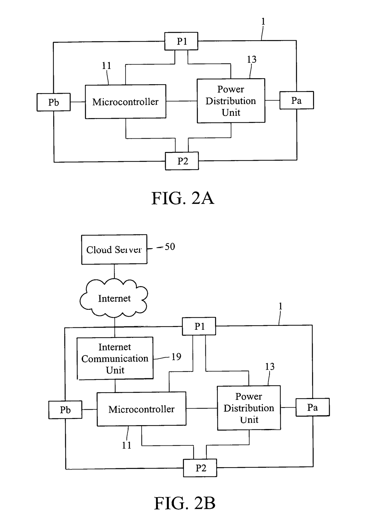
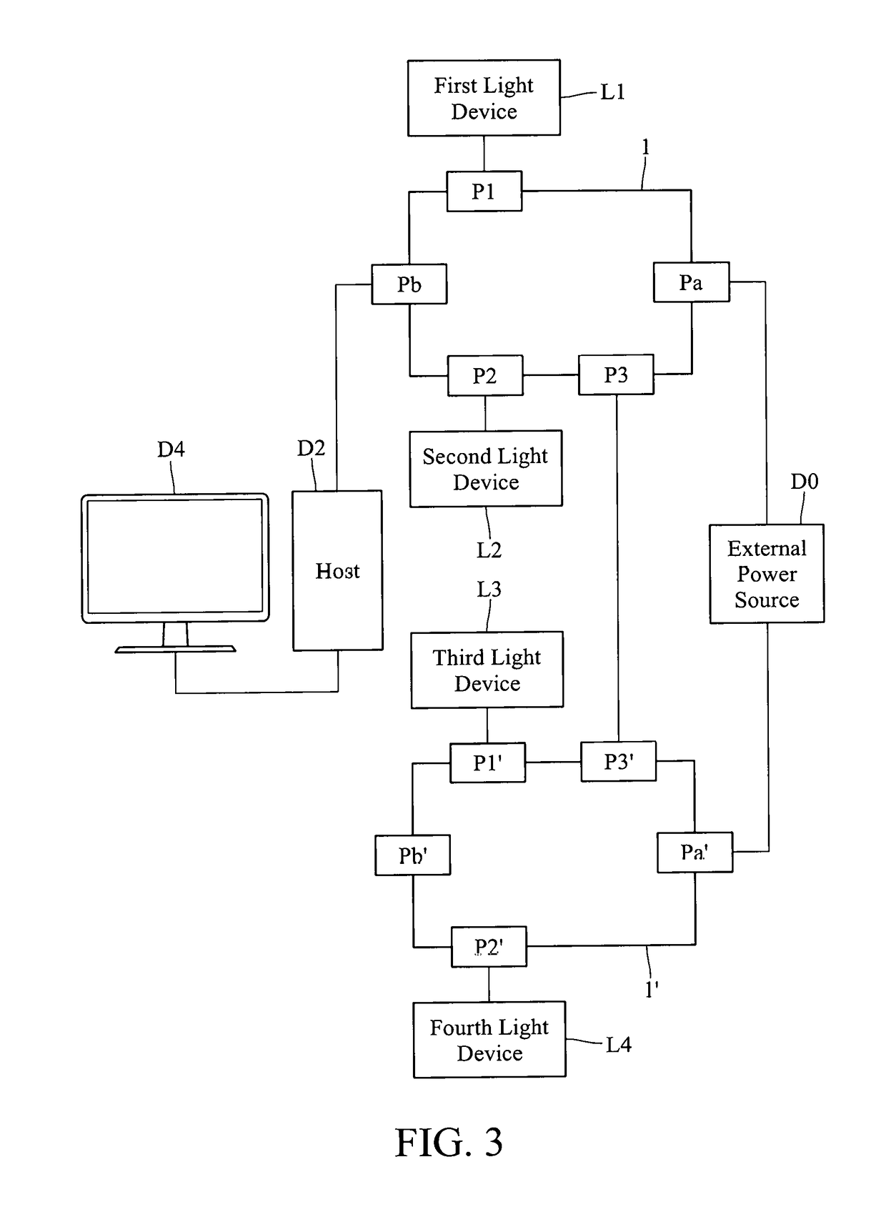
[0027]In the following, three embodiments of the light control system of the present disclosure will be described sequentially, together with their corresponding light control method. In the first embodiment, the light control system uses the corresponding configuration based on different types of the light devices and controls the light device to emit colored light according to the multimedia signal sent from the host. In the second embodiment, the light control system uses the camera device to obtain the positions of light devices and the display screen of the display device and ...


PUM


Abstract

A light control system comprises a power connecting port, a host connecting port, a first light connecting port, a second light connecting port, a microcontroller and a power distribution unit. The power connecting port electrically connects to an external power source to provide the power to drive a plurality of light devices. The host connecting port is configured to receive a multimedia signal from a host. The first light connecting port and the second light connecting port electrically connect to a first light device and a second light device respectively. The microcontroller is configured to identify device types and generate two dimming signals according to configurations corresponding to the device types and the multimedia signal. The power distribution unit converts the two dimming signals to two driving signals for controlling the first light device and the second light device to emit colored lights associated with the multimedia signals.

Description

CROSS-REFERENCE TO RELATED APPLICATIONS[0001]This non-provisional application claims priority under 35 U.S.C. § 119(a) on Patent Application No(s). 62 / 511,873 filed in the U.S. on May 26, 2017, the entire contents of which are hereby incorporated by reference.TECHNICAL FIELD[0002]This disclosure relates to a light control system and a light control method, particularly a light control system that can dynamically adjust the color of the light and the method thereof.RELATED ART[0003]With the rise of eSports, in addition to enhancing the performance of various hardware, high-level gaming computers also adding a rich lighting presentation to enhance the user experience. For example, the LED (Light-Emitting Diode) strips that emit single or multiple colors of light are installed on the case, the motherboard, the display card, the memory, the fan, the keyboard, the mouse, or even the power supply. It is expected that the illuminating devices installed in different positions will give the ...

Claims


Application Information

Patent Timeline
IPC IPC(8): H05B33/08H05B37/02G06K9/00H05B44/00
CPCH05B33/0854H05B37/0272H05B37/0227H05B37/0236H05B33/0821G06K9/00624H05B47/10H05B45/20H05B47/105H05B47/135H05B47/165H05B47/12
Inventor CHEN, CHIEN-LUNGLU, PU-SHIHFENG, KUEI-YUN
Owner COOLER MASTER TECH
Features
  • Generate Ideas
  • Intellectual Property
  • Life Sciences
  • Materials
  • Tech Scout
  • Unparalleled Data Quality
  • Higher Quality Content
  • 60% Fewer Hallucinations
Learn More