Cochlear implants having mri-compatible magnet apparatus and associated methods

a cochlear implant and magnet apparatus technology, applied in the field of implantable cochlear implantable cochlear stimulation (or “ ics”) systems, can solve the problems of inconvenient headpiece mounting, inability to properly mount the headpiece to the patient's head, and undesirable increase in the size and weight of the headpi

Active Publication Date: 2018-12-27
ADVANCED BIONICS AG
View PDF0 Cites 25 Cited by
  • Summary
  • Abstract
  • Description
  • Claims
  • Application Information

AI Technical Summary

Benefits of technology

[0008]There are a number of advantages associated with such apparatus and methods. For example, a strong magnetic field, such as an MRI magnetic field, will not demagnetize the magnet apparatus. Nor will it generate a significant amount of torque on the magnet apparatus and associated cochlear implant. As a result, surgical removal of the cochlear implant magnet prior to an MRI procedure, and then surgically replacement thereafter, is not required. Moreover, in the absence of the strong magnetic field, the magnetic attraction between rotatable magnets in the magnet apparatus will not cause the magnets to rotate into an undesirable N-S orientation.

Problems solved by technology

Such magnets are not compatible with magnetic resonance imaging (“MRI”) systems.
The implant magnet produces a magnetic field M in a direction that is perpendicular to the patient's skin and parallel to the axis A, and this magnetic field direction is not aligned with, and may be perpendicular to (as shown), the direction of the MRI magnetic field B. The misalignment of the interacting magnetic fields M and B is problematic for a number of reasons.
The weak magnetic attraction resulting from the misalignment of the magnetic fields prevents the headpiece from properly mounting to the patient's head.
The present inventors have determined, however, that the associated increase in the size and weight of the headpiece is undesirable.
Nor will it generate a significant amount of torque on the magnet apparatus and associated cochlear implant.

Method used


Image

  • Cochlear implants having mri-compatible magnet apparatus and associated methods
  • Cochlear implants having mri-compatible magnet apparatus and associated methods
  • Cochlear implants having mri-compatible magnet apparatus and associated methods

Examples


Embodiment Construction

[0043]The following is a detailed description of the best presently known modes of carrying out the inventions. This description is not to be taken in a limiting sense, but is made merely for the purpose of illustrating the general principles of the inventions.

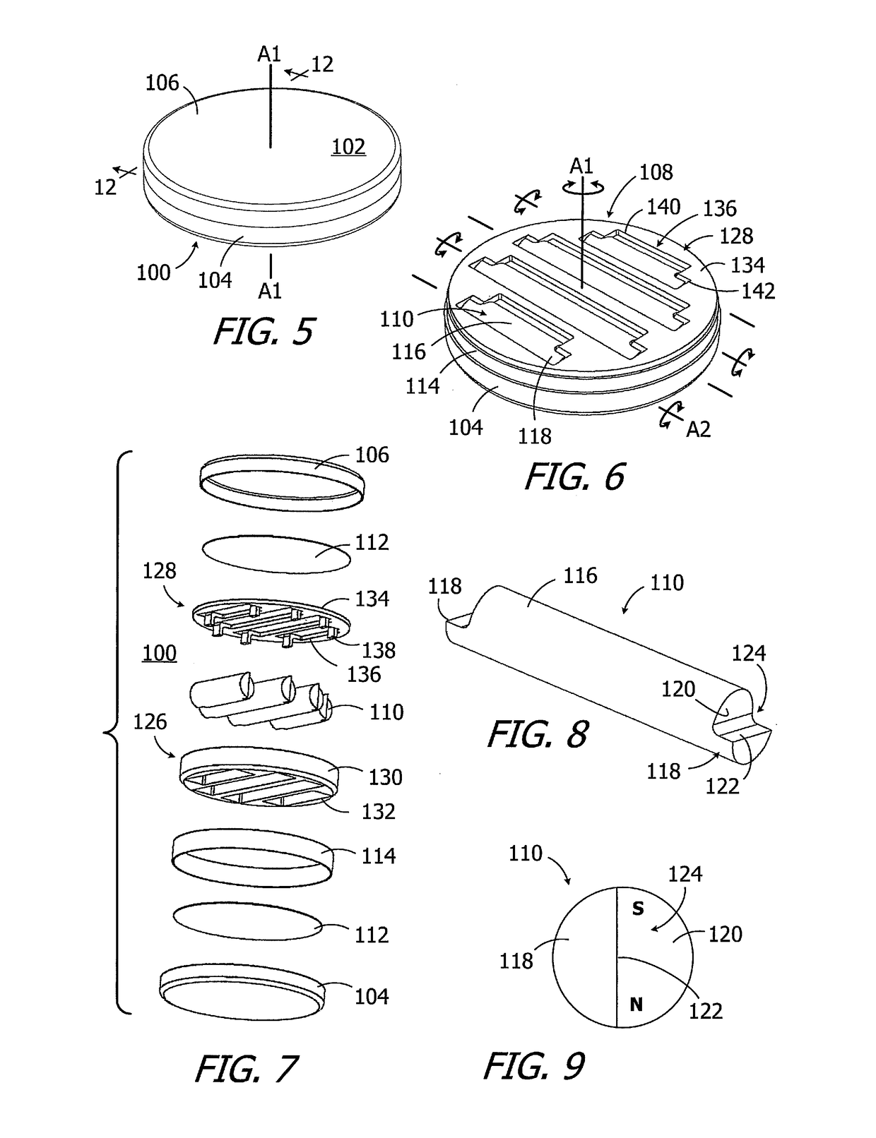
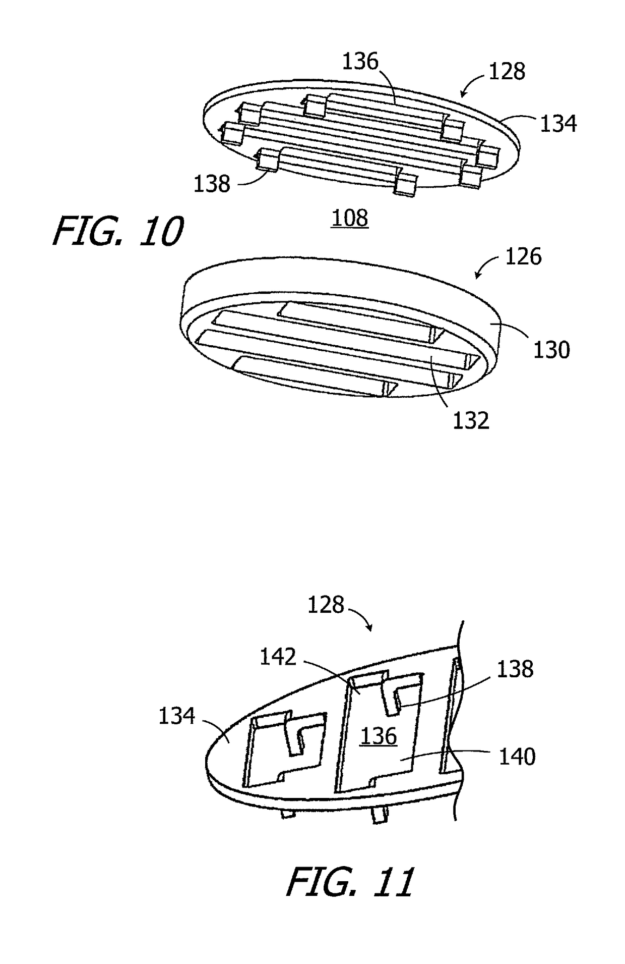
[0044]As illustrated for example in FIGS. 5-9, an exemplary magnet apparatus 100 includes a case 102, with base 104 and a cover 106, a magnet frame 108, and a plurality of elongate diametrically magnetized magnets 110 within the frame that define a N-S direction. The exemplary case 102 is disk-shaped and defines a central axis A1, which is also the central axis of the magnet frame 108. The magnet frame 108 is freely rotatable relative to the case 102 about the central axis A1 over 360°. The magnets 110 rotate with the magnet frame 108 about the central axis A1. Each magnet 110 is also rotatable relative to the magnet frame 108 about its own longitudinal axis A2, with the frame limiting rotation to less than 360° in the manner ...


PUM


Abstract

A cochlear implant including a cochlear lead, an antenna, a stimulation processor, and a magnet apparatus, associated with the antenna, including a case defining a central axis, a magnet frame within the case and rotatable about the central axis of the case, and a plurality of diametrically magnetized magnets that are located in the magnet frame, the magnets defining a longitudinal axis and a N-S direction and being rotatable about the longitudinal axis relative to the magnet frame and biased by the magnet frame to a predetermined N-S rotational orientation.

Description

BACKGROUND1. Field[0001]The present disclosure relates generally to the implantable portion of implantable cochlear stimulation (or “ICS”) systems.2. Description of the Related Art[0002]ICS systems are used to help the profoundly deaf perceive a sensation of sound by directly exciting the intact auditory nerve with controlled impulses of electrical current. Ambient sound pressure waves are picked up by an externally worn microphone and converted to electrical signals. The electrical signals, in turn, are processed by a sound processor, converted to a pulse sequence having varying pulse widths and / or amplitudes, and transmitted to an implanted receiver circuit of the ICS system. The implanted receiver circuit is connected to an implantable electrode array that has been inserted into the cochlea of the inner ear, and electrical stimulation current is applied to varying electrode combinations to create a perception of sound. The electrode array may, alternatively, be directly inserted ...

Claims


Application Information

Patent Timeline
Patent Type & Authority Applications(United States)
IPC IPC(8): A61N1/36A61N1/08A61N1/375H04R25/00
CPCA61N1/36038A61N1/08A61N1/375H04R25/606H04R2225/67
Inventor LEE, SUNG JINWALTER, JERYLE L.SMITH, JAMES GEORGE ELCOATEGOMMEL, ULIREED, STEPHANIE M.
Owner ADVANCED BIONICS AG
Why Eureka
Try Eureka