
Surface potential measurement of dielectric materials in plasma

a dielectric material and surface potential technology, applied in the direction of material electrochemical variables, instruments, material analysis, etc., can solve the problems of inability to obtain measurements that agree with theoretical predictions, prior test methods have not been able to accurately measure the surface potential of dielectric materials having dusty surface conditions, and the risk of destructive static discharg

Active Publication Date: 2018-12-27
UNIV OF SOUTHERN CALIFORNIA
View PDF0 Cites 4 Cited by
  • Summary
  • Abstract
  • Description
  • Claims
  • Application Information

AI Technical Summary

Benefits of technology

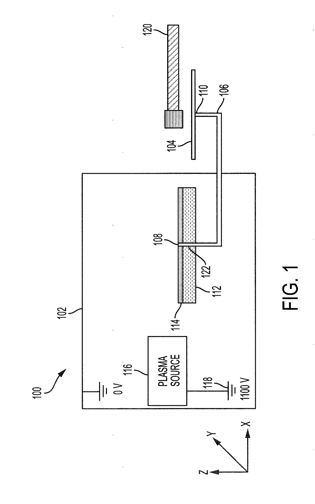
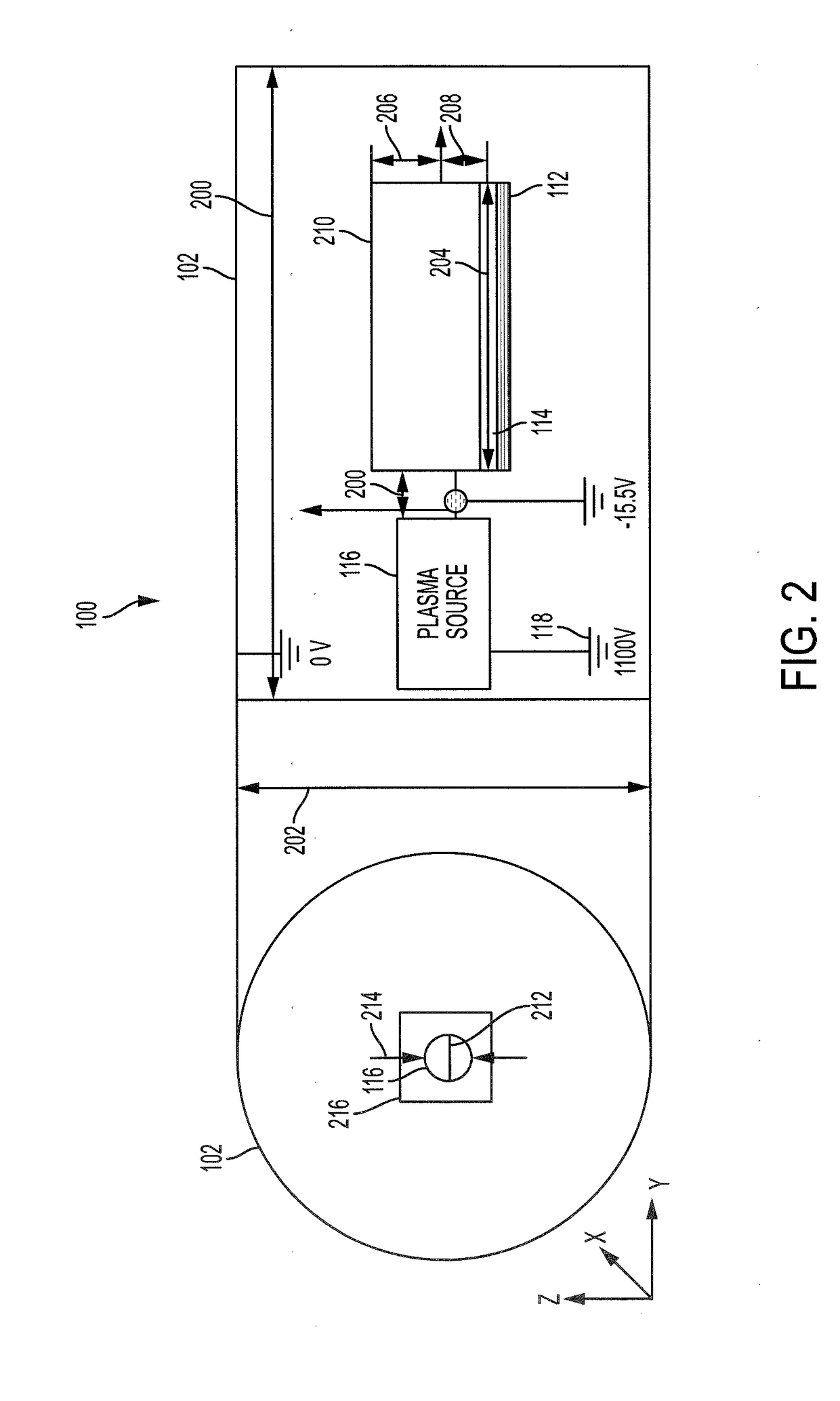
This patent describes a system and method for measuring the voltage of a dielectric material in plasma. The system includes a vacuum chamber and a conductive probe with a first end in contact with the dielectric material and a second end in electrical communication with an electrostatic receiver outside the chamber. A non-contact electrostatic voltmeter measures the potential of the receiver that corresponds to the dielectric potential of the material at the first conductive probe's location. The technical effect is the ability to accurately measure the voltage of dielectric material in plasma, which is difficult to do using other methods.

Problems solved by technology

Working in a charged suit in the near vacuum of space or other near vacuum environments in which plasmas predominate the surrounding medium introduces a risk of destructive static discharge.
However, prior test methods have been unable to accurately measure surface potential of dielectric materials having dusty surface conditions in plasma.
Researchers have been unable to obtain measurements that agree with theoretical predictions.
Hence, designers of dielectric coverings or other articles for use in dusty plasma environments have been deprived of empirical data on which to base their designs.
In addition, measurements of surface potential using a non-contacting probe in a vacuum chamber, such as, for example, a Trek™ electrostatic voltmeter (ESVM) have also yielded unreliable measurements, because the need to turn off the plasma source to read the probe result in transient effects that introduce measurement errors.

Method used


Image

  • Surface potential measurement of dielectric materials in plasma
  • Surface potential measurement of dielectric materials in plasma
  • Surface potential measurement of dielectric materials in plasma

Examples


Embodiment Construction

[0024]The potential of a clean conductor in plasma can be obtained by measuring its current-voltage characteristics. The potential of a solid dielectric surface in plasma can be measured by methods utilizing contacting probes or a Trek™ non-contacting electrostatic voltmeter (ESVM). The surface potential of a dust layer can also be measured using a Trek™ non-contacting ESVM. However, the potential of the surface underneath a dust layer has not been measured due to a lack of viable experimental methods. Currently, there is very limited knowledge on plasma charging of a dust covered surface.

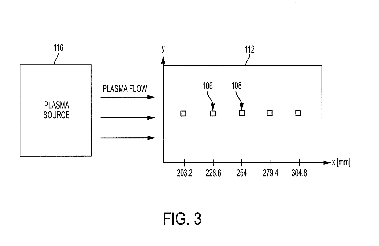
[0025]The present disclosure describes systems and methods for measuring a charging of a conducting surface covered by a thin layer of dielectric dust grains in plasma. The method utilizes conducting wires embedded within the dust layer and a Trek™ non-contacting ESVM, which directly measures the potential of a dust covered conducting plate and the potentials within the dust layer. In the present d...


PUM

PropertyMeasurementUnit
angle of attackaaaaaaaaaa
diameteraaaaaaaaaa
diameteraaaaaaaaaa

Abstract

A system for voltage measurement of dielectric material in plasma includes a vacuum chamber. The system also includes an electrostatic receiver located outside of the vacuum chamber. The system also includes a conductive probe having a first terminus in contact with the dielectric material in the vacuum chamber and a second terminus in electrical communication with the electrostatic receiver. The system also includes a non-contact electrostatic voltmeter configured to measure a floating potential of the electrostatic receiver that corresponds to a dielectric potential of the dielectric material at a location in contact with the first terminus of the conductive probe.

Description

CROSS-REFERENCE TO RELATED APPLICATIONS[0001]This application claims the benefit and priority of U.S. Provisional Application No. 62 / 524,400, entitled “SURFACE POTENTIAL MEASUREMENT OF DIELECTRIC MATERIALS IN PLASMA,” filed on Jun. 23, 2017, the entire disclosure of which is hereby incorporated by reference herein in its entirety.BACKGROUND1. Field[0002]The present disclosure relates to systems and methods for determining voltage potential of dielectric materials in plasma and, more particularly, for determining surface potential of dust in an outer space environment.2. Description Of The Related Art[0003]Spacecraft charging has been a subject of extensive investigations over the past decades, and dust charging has been a subject of substantial studies in recent years. However, most studies on spacecraft charging have focused on the charging of a “clean” surface in a plasma, and previous studies on dust charging have focused on the charging of single, isolated dust grains. When a sp...

Claims


Application Information

Patent Timeline
Patent Type & Authority Applications(United States)
IPC IPC(8): G01N27/26G01R29/12G01R29/24G01N27/62
CPCG01N27/26G01R29/12G01R29/24G01N27/62G01N27/221G01R19/0061G01R19/0084G01R15/165
Inventor CHOU, KEVIN
Owner UNIV OF SOUTHERN CALIFORNIA
Learn More