Check patentability & draft patents in minutes with Patsnap Eureka AI!

Sensor Calibration System

a technology of calibration system and sensor, which is applied in the direction of process and machine control, using reradiation, instruments, etc., can solve the problem of long time-consuming operation of mines, and achieve the effect of accurate obstacle detection

Active Publication Date: 2018-12-27
HITACHI LTD
View PDF0 Cites 19 Cited by
  • Summary
  • Abstract
  • Description
  • Claims
  • Application Information

AI Technical Summary

Benefits of technology

The present invention provides a way to accurately detect obstacles using multiple sensors by adjusting their parameters and detecting the relative position between them. This can help improve the accuracy of obstacle detection.

Problems solved by technology

However, since a traveling road at a mine through which a dump truck travels is an off-road and there are many rough roads, when causing a dump truck to autonomously travel and perform an unmanned operation, there is a risk of a collision with an obstacle such as a mud wall or another vehicle, if an obstacle exists on the traveling road and an autonomous traveling unmanned dump truck comes into contact with the obstacle and stops, the operation of the mine is stopped for a long time.

Method used


Image

  • Sensor Calibration System
  • Sensor Calibration System
  • Sensor Calibration System

Examples


example 1

[0022]In this embodiment, an embodiment is for obtaining the relative position and orientation of the sensor position attached to the vehicle and the sensor vehicle position of the vehicle position.

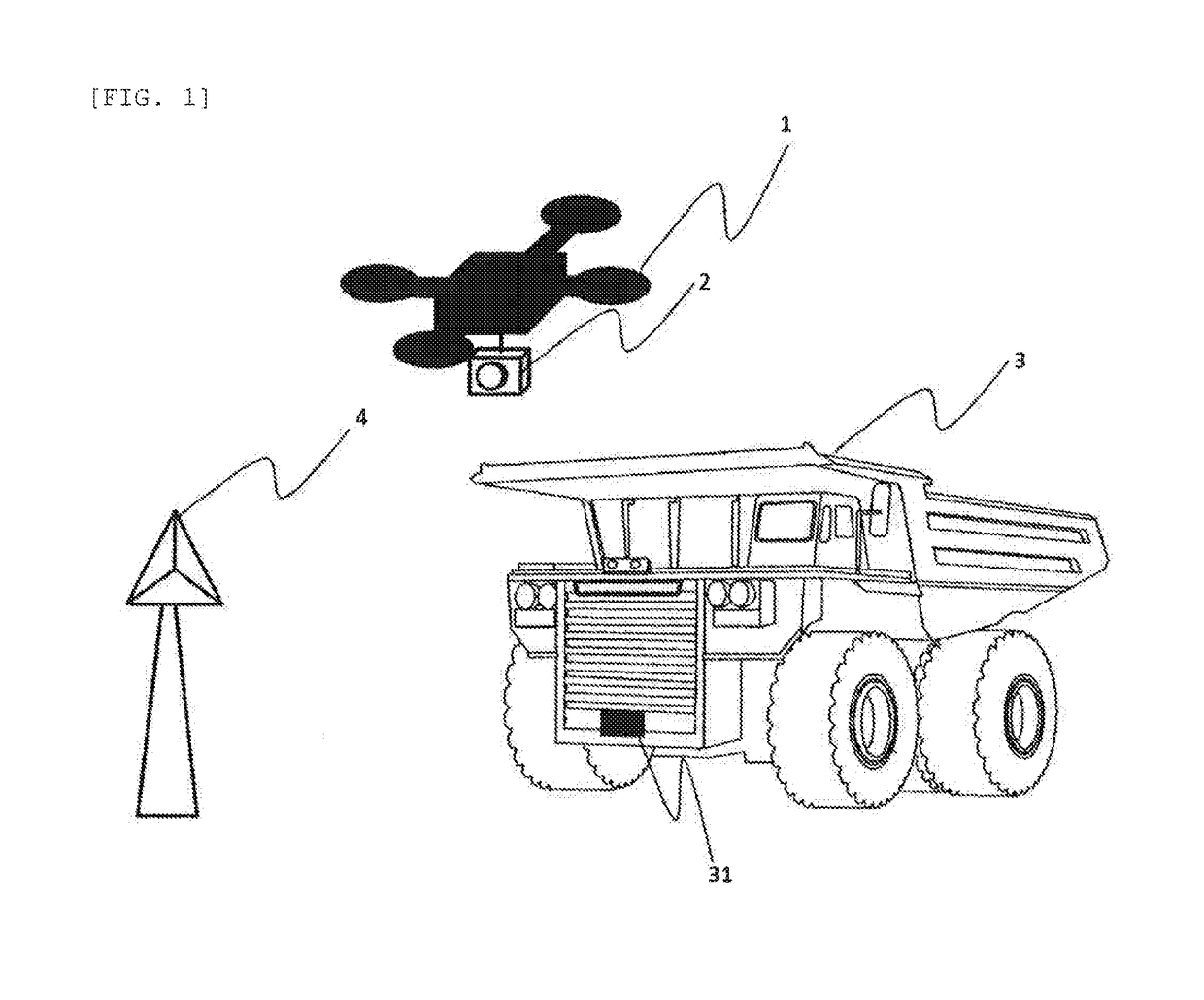
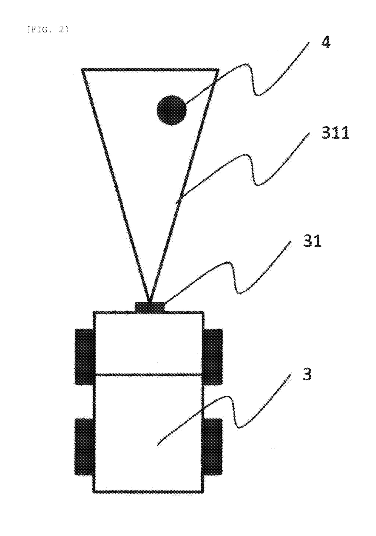
[0023]FIG. 1 is a view illustrating an example of a scene utilizing this embodiment. The relative position and the orientation between the vehicle 3 and the attachment position of the first measurement section 31 attached to the vehicle 3 are obtained. At this time, it is assumed that the first measurement section 31 uses an external sensor capable of detecting the position of an arbitrary obstacle such as a millimeter wave radar, a Lidar, a camera, a stereo camera, and a TOF sensor. In the present embodiment, a first landmark 4 is installed in a measuring range 311 of the first measurement section. A view illustrating this situation in a bird's-eye view is illustrated in FIG. 2.

[0024]At this time, it is desirable that the first landmark 4 can be easily measured by the first measurement s...

example 2

[0038]The present embodiment is an embodiment aimed at obtaining the relative position of a plurality of sensors attached to a vehicle. FIG. 6 illustrates an example in which the first measurement section 31 and the second measurement section 32 are attached. The relative position and orientation of the first measurement section 31 and the second measurement section 32 attached to the vehicle 3 are obtained. At this time, it is assumed that the first measurement section and the second measurement section use an external sensor capable of detecting the position of an arbitrary obstacle such as a millimeter wave radar, a Lidar, a camera, a stereo camera, and a TOF sensor.

[0039]At this time, there is no problem even if the first measurement section 31 and the second measurement section 32 are of different types of external sensors. In the present embodiment, the first landmark 4 is installed, in the measuring range 311 of the first measurement section, and the second landmark 5 is inst...


PUM


Abstract

When a combination of a plurality of sensors is used for obstacle detection, the present invention is to detect the relative positions of the sensors, to correct inter-sensor parameters, and to provide accurate obstacle detection. This calibration system is provided with a first landmark detecting unit for detecting the position of a first landmark from three-dimensional shape information; a landmark associating unit for determining a correspondence relation, between the first landmark position detected by the first landmark detecting unit and an attachment position to the vehicle of the first landmark estimated by a vehicle landmark relative position estimating unit; and a vehicle sensor relative orientation estimating unit for estimating the relative position and orientation of the vehicle and a first measurement section based on the information from the vehicle landmark relative position estimating unit and a landmark associating unit.

Description

TECHNICAL FIELD[0001]The present invention relates to an inter-sensor calibration system for autonomous traveling vehicles, for example.BACKGROUND ART[0002]Generally in mines, mining work machines such as hydraulic shovels and dump trucks are used for excavation work and transportation work of earth and sand. For the mining work machines used at mines, an unmanned operation is required from the viewpoint of safety and cost reduction. In the dump truck, because the amount of earth and sand transported per unit time is directly related to the degree of progress of mining, an efficient operation is required. Therefore, in order to transport a large amount of earth and sand efficiently to the outside of the mining site, a mining system which uses an autonomous dump truck capable of performing a continuous operation has been required.[0003]However, since a traveling road at a mine through which a dump truck travels is an off-road and there are many rough roads, when causing a dump truck ...

Claims


Application Information

Patent Timeline
Patent Type & Authority Applications(United States)
IPC IPC(8): G01S7/40G01S13/86G01S13/93G08G1/16G01S13/931
CPCG01S7/40G01S13/86G01S13/931G08G1/16G01S13/862G01S13/865G01S13/867G01S13/89G01S13/874G08G1/165G05D1/0234G01S2013/9322G01S2013/9329G01S2013/9324G01S2013/93274G01S2013/9323G01S2013/93271G01S7/4091G05D1/02
Inventor HIEIDA, YUSUKENAKA, TAKUYA
Owner HITACHI LTD
Features
  • R&D
  • Intellectual Property
  • Life Sciences
  • Materials
  • Tech Scout
  • Unparalleled Data Quality
  • Higher Quality Content
  • 60% Fewer Hallucinations
Learn More