Substrate holding member

a technology of holding member and substrate, which is applied in the direction of semiconductor/solid-state device manufacturing, basic electric elements, electrical equipment, etc., can solve the problems of peeling or cracking between the base and the protection film during long-term use, difficult to hold the substrate with a satisfactory flatness, peeling or cracking, etc., to inhibit the peeling of the holding member from the base

Active Publication Date: 2018-12-27
NGK SPARK PLUG CO LTD
View PDF0 Cites 0 Cited by
  • Summary
  • Abstract
  • Description
  • Claims
  • Application Information

AI Technical Summary

Benefits of technology

[0026]In this case, the recess is formed at the upper surface of the base, and the holding member is formed in the recess, thereby inhibiting peeling of the holding member from the base.

Problems solved by technology

However, when the convex part has the slender cylindrical shape as described in Patent Document 1, breakage of the convex part may occur due to a sliding force that repeatedly acts on the contact face between the convex part and the base, which makes it difficult to hold the substrate with a satisfactory flatness over a long term.
Meanwhile, when the protection film is formed over the entire surface of the base as described in Patent Document 2, a difference in physical properties between the base and the protection film may cause peeling or cracking between the base and the protection film during long-term use.
Such stress is propagated into the base under the protection film, and causes peeling or cracking.
Such peeling or cracking of the protection film may cause generation of particles, which makes it difficult to hold the substrate with a satisfactory flatness over a long term.

Method used


Image

  • Substrate holding member
  • Substrate holding member
  • Substrate holding member

Examples


first embodiment

[0036]A substrate holding member 1 according to the present invention will be described with reference to the drawings.

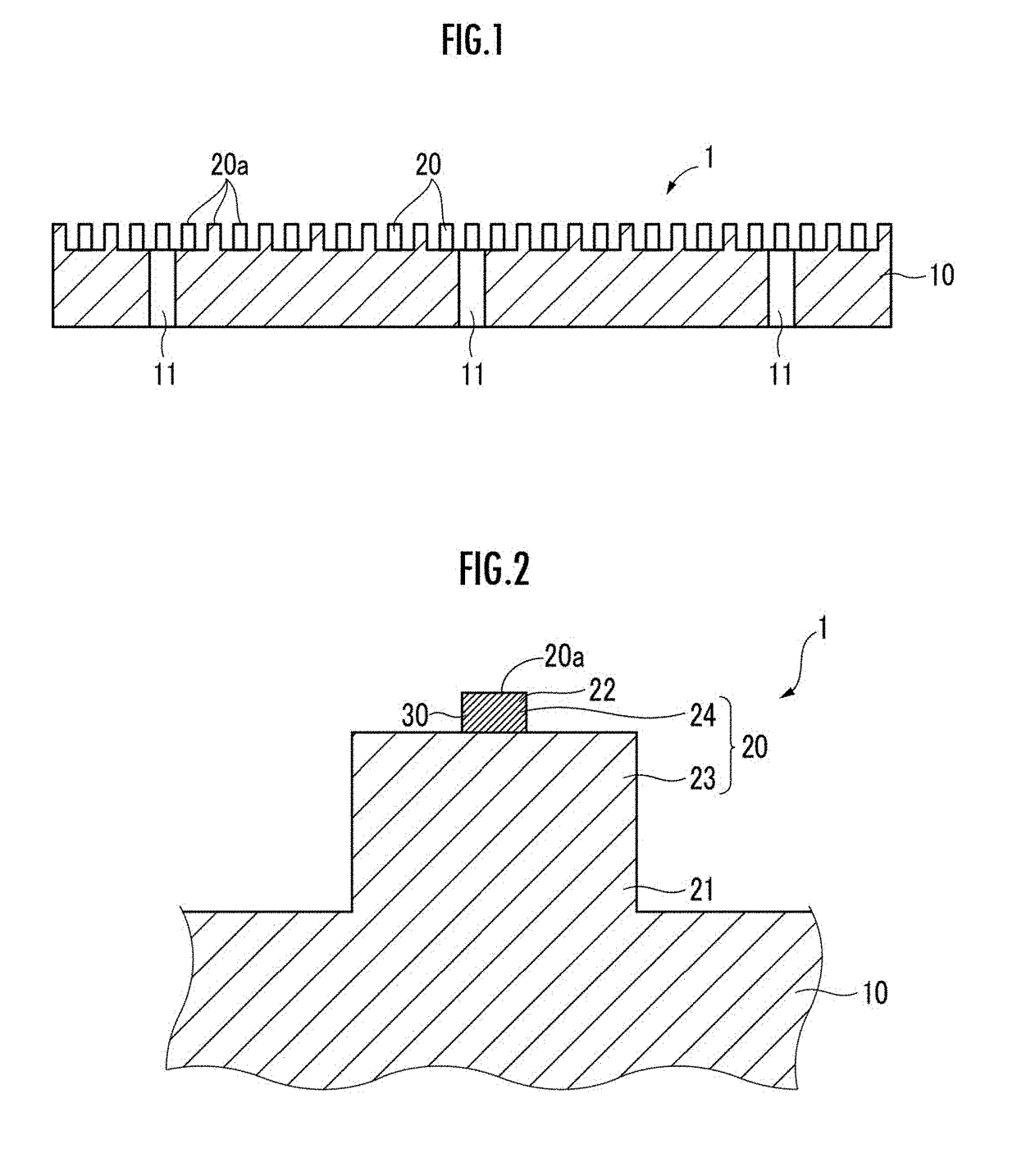
[0037]As shown in a cross-sectional view of FIG. 1, the substrate holding member 1 includes: a disk-shaped base 10; and a plurality of convex parts (projecting portions, pins) 20 which are formed on an upper surface of the base 10, and hold a wafer (substrate), which is not shown, at top surfaces 20a thereof.

[0038]In the substrate holding member 1, as shown in a partially enlarged cross-sectional view of FIG. 2, each convex part 20 has: a root portion 21 extending from the upper surface of the base 10; and a top portion 22 formed on the root portion 21 and including the top surface 20a. In the convex part 20, a cross-sectional area S1 of the root portion 21 in a horizontal direction (right-left direction in FIG. 2) along the upper surface of the base 10 is larger than a cross-sectional area S2 of the top portion 22 in the horizontal direction.

[0039]At least a portio...

second embodiment

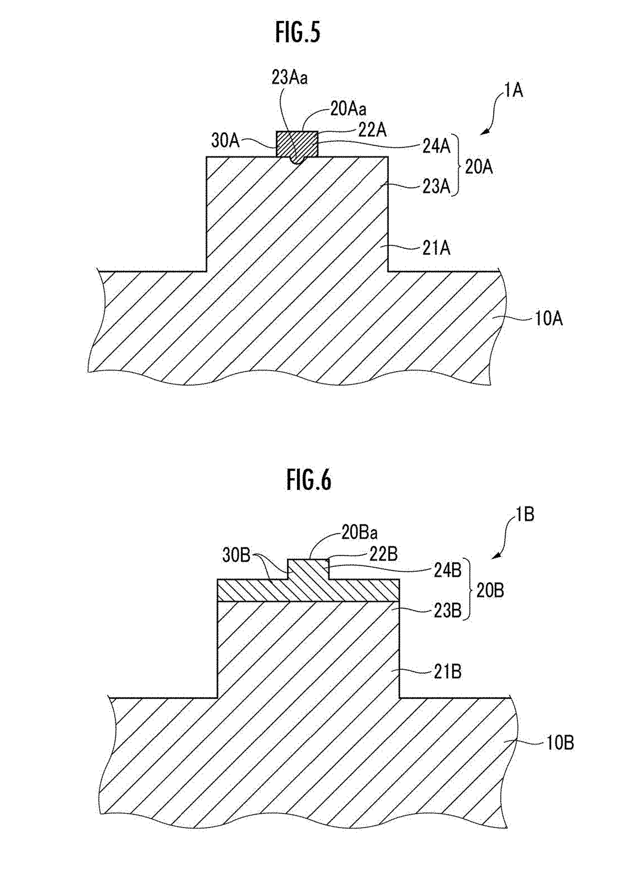
[0064]Next, a substrate holding member 1A according the present invention will be described with reference to the drawing. As shown in FIG. 5, the substrate holding member 1A is different from the aforementioned substrate holding member 1 only in that a holding member 30A is formed also in a recess 23Aa formed at an upper surface of a lower part 23A.

[0065]Thus, the holding member 30A is formed in such a shape that a portion thereof formed in the recess 23Aa of the lower part 23A and the entirety of an upper part 24A are integrated with each other. A cross-sectional shape of the recess 23Aa in the vertical direction is not particularly limited, and may be a semi-circle, a semi-ellipse, a rectangle, or the like, or may be such a shape that an inner portion thereof laterally expands as compared with an opening thereof. The recess 23Aa preferably has a depth of 0.01 to 0.2 mm, and an opening width of 0.02 to 0.2 mm.

[0066]The holding member 30A may be formed as follows. That is, after th...

third embodiment

[0069]Next, a substrate holding member 1B according to the present invention will be described with reference to the drawing. As shown in FIG. 6, the substrate holding member 1B is different from the aforementioned substrate holding member 1 only in that an upper portion of a lower part 23B is made of the same material as an upper part 24B forming a portion of the holding member 30B.

[0070]Thus, the holding member 30B is formed in such a shape that the upper portion of the lower part 23B and the entirety of the upper part 24B are integrated with each other. A lower portion of the lower part 23B is formed continuously from the base 10. The thickness of the holding member 30B at the upper portion of the lower part 23B is preferably 0.01 to 0.2 mm.

[0071]According to the substrate holding member 1B described above, like the aforementioned substrate holding member 1, the wafer can be held with a satisfactory flatness over a long term.

[0072]Since the holding member 30B forms the upper part...


PUM


Abstract

A substrate holding member includes a base, and a plurality of convex parts formed at an upper surface of the base and configured to hold a substrate at top surfaces thereof. Each convex part has a root portion extending from the upper surface of the base, and a top portion formed on the root portion and including the top surface. In each convex part, a cross-sectional area of the root portion is larger than a cross-sectional area of the top portion. At least a portion including the top surface of the top portion is formed of a holding member made of a material having a greater Young's modulus than a material forming the base. The respective holding members are spaced apart from each other.

Description

CROSS REFERENCE TO RELATED APPLICATION[0001]The present application claims priority to Japanese Patent Application No. 2017-124440 which was filed on Jun. 26, 2017 and Japanese Patent Application No. 2018-062113 which was filed on Mar. 28, 2018, the disclosures of which are herein incorporated by reference in their entireties.BACKGROUND OF THE INVENTIONField of the Invention[0002]The present invention relates to a substrate holding member, and particularly to a substrate holding member such as a vacuum chuck for holding a substrate such as a wafer.Description of Related Art[0003]In a semiconductor manufacturing apparatus, a substrate holding member is used as a member for holding a substrate such as a wafer. In the substrate holding member, a plurality of convex parts are formed at a surface of a base, and a wafer is held at top surfaces (tip surfaces) of the convex parts.[0004]In order to minimize the contact area between each convex part and the substrate, the area of the top surf...

Claims


Application Information

Patent Timeline
Patent Type & Authority Applications(United States)
IPC IPC(8): H01L21/683H01L21/687
CPCH01L21/6838H01L21/68757H01L21/68728H01L21/6875H01L21/683
Inventor ONODERA, NORIOTESHIMA, TAKASHI
Owner NGK SPARK PLUG CO LTD
Why Eureka
Try Eureka