
Force damping dental bridge assembly with synthetic periodontal ligament fibers

a technology of synthetic periodontal ligament fibers and dental bridges, which is applied in dental prosthetics, dental surgery, medical science, etc., can solve the problems of not allowing the implant to resiliently flex, pathologic mobility, and destroying the patient's mandible as well as the bridge assembly

Active Publication Date: 2019-01-03
CLARK JR PAUL KENNETH
View PDF2 Cites 0 Cited by
  • Summary
  • Abstract
  • Description
  • Claims
  • Application Information

AI Technical Summary

Benefits of technology

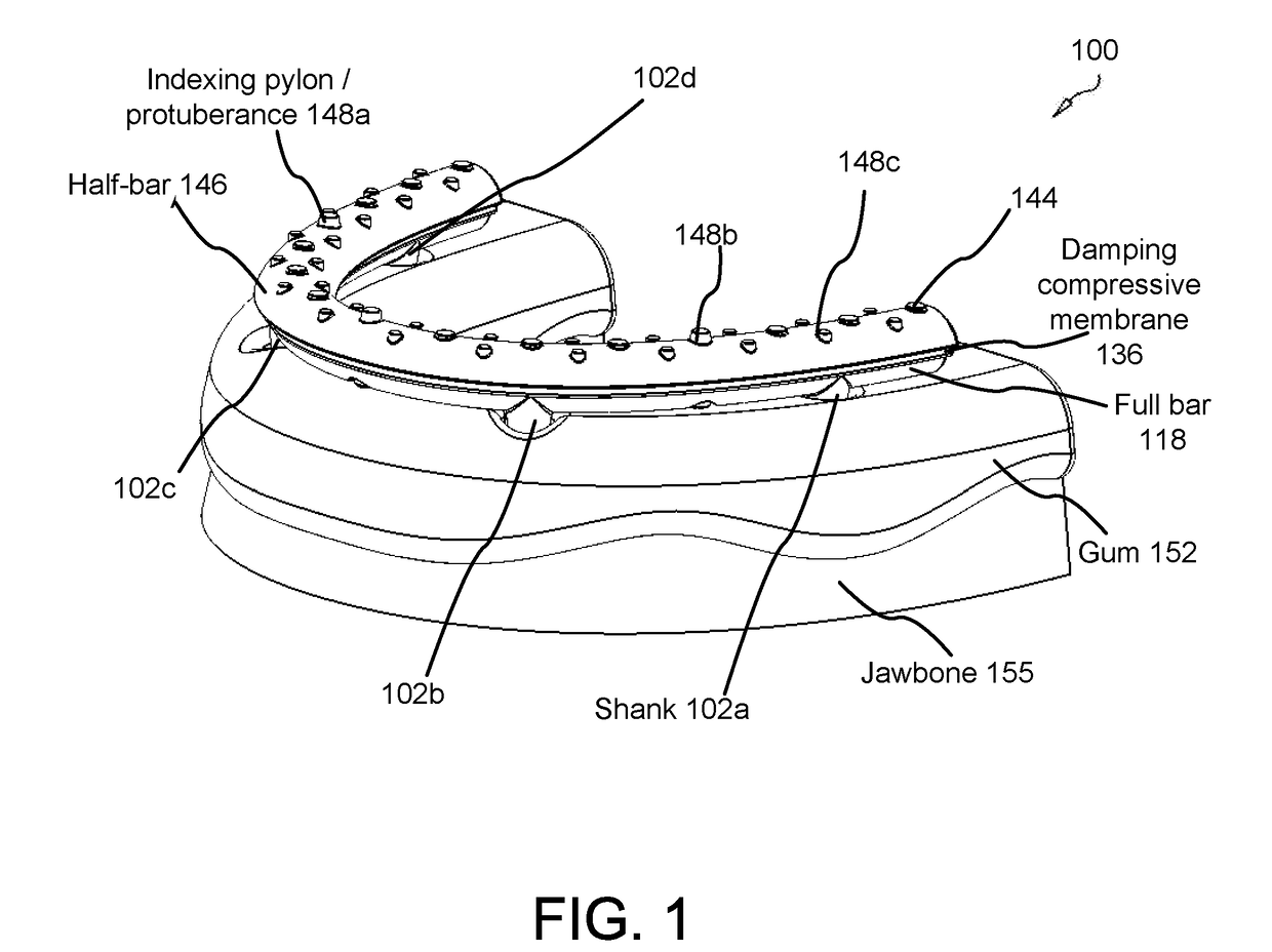
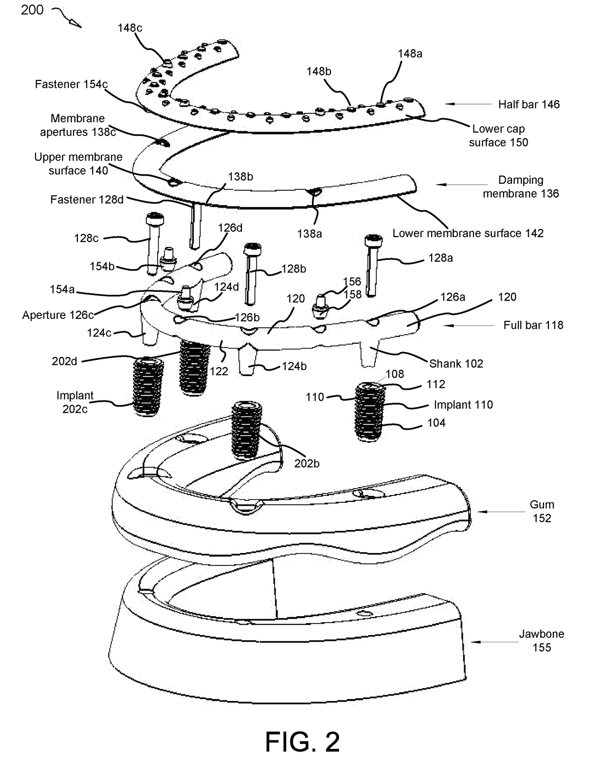
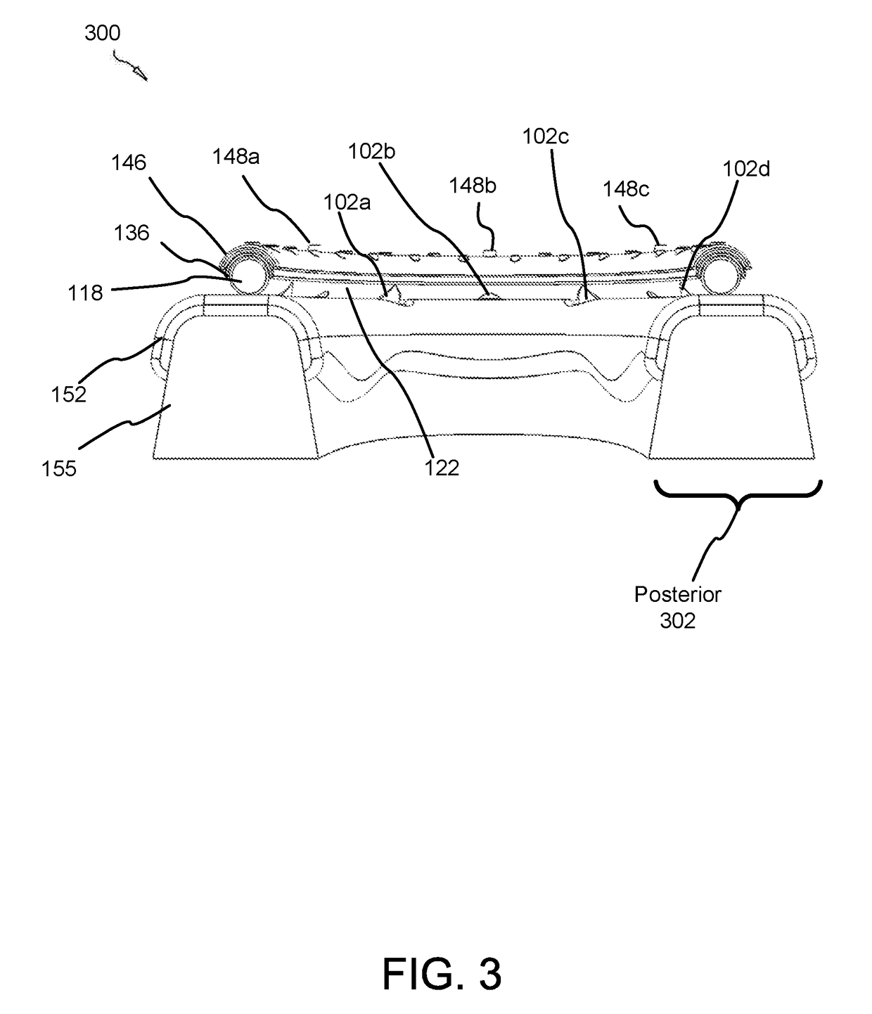
The present invention provides a force-damping dental bridge assembly that can damp compressive, tensile, and lateral forces on a tooth and jawbone through the use of synthetic periodontal ligament fibers. The assembly includes an arcuate full bar and shanks that can be inserted into implants in a patient's mouth, a damping membrane that is positioned above the full bar and detachably affixed thereto, and an arcuate half-bar that can be engaged with the damping membrane. The assembly can be easily detached for cleaning purposes and can provide a comfortable and effective solution for patients who require dental implants.

Problems solved by technology

However, a significant reason for breakage and loosening of conventional dental implants is that most prior art apparati do not allow the implant to resiliently flex relative to the jaw bone.
This concentration of stress on the bone results in the physiological phenomenon known as resorption and causes pathologic mobility—or mobility which is destructive the patient's mandible as well as the bridge assembly.
Furthermore, patients face the difficult prospect of cleaning dental bridge assemblies which are removable.
There exists no efficient means in the art of cleaning a dental bridge assembly.

Method used


Image

  • Force damping dental bridge assembly with synthetic periodontal ligament fibers
  • Force damping dental bridge assembly with synthetic periodontal ligament fibers
  • Force damping dental bridge assembly with synthetic periodontal ligament fibers

Examples


Embodiment Construction

[0033]Reference throughout this specification to “one embodiment,”“an embodiment,” or similar language means that a particular feature, structure, or characteristic described in connection with the embodiment is included in at least one embodiment of the present invention. Thus, appearances of the phrases “in one embodiment,”“in an embodiment,” and similar language throughout this specification may, but do not necessarily, all refer to the same embodiment.

[0034]Furthermore, the described features, structures, or characteristics of the invention may be combined in any suitable manner in one or more embodiments. In the following description, numerous specific details are provided to provide a thorough understanding of embodiments of the invention. One skilled in the relevant art will recognize, however, that the invention may be practiced without one or more of the specific details, or with other methods, components, materials, and so forth. In other instances, well-known structures, ...


PUM


Abstract

A force damping dental bridge assembly which damps compressive, tensile, and lateral forces on a prosthetic tooth and jawbone through use of synthetic periodontal ligament fibers in the form of a damping membrane. Multiple layers of arcuate components and Morse taper interconnections secure the assembly. A threaded implant that penetrates the jawbone defining a tapered, conical inner cavity which receives a shank protruding downwardly from a full bar. An arcuate damping membrane positions on the bar and a half-bar positions over the membrane; whereby the damping membrane is sufficiently resilient to enable lateral and axial movements by the prostheses affixed to the half-bar. A plurality of protuberances extend from an upper surface of the half-bar to enable sculpting and affixation of prostheses thereon; and whereby a plurality of fasteners detachably connect the prostheses to the bar and / or implants in a snap-fit relationship that can be detached with an implement adapted to unsnap the assembly from a patient's mouth.

Description

FIELD OF THE INVENTION[0001]This invention relates to a force damping dental bridge assembly, and more particularly relates to a bridge assembly that damps compressive, tensile, and lateral forces on a tooth and jawbone through use of synthetic periodontal ligament fibers. Multiple layers of arcuate components and one or more Morse taper interconnection(s) secure the assembly. A threaded implant that penetrates the jawbone defining a tapered, conical inner cavity which receives a shank protruding downwardly from a full bar. An arcuate damping membrane positions on the bar and a half-bar positions over the membrane; whereby the damping membrane is sufficiently resilient to enable lateral and axial movements by prostheses affixed to the half-bar. A plurality of protuberances / indexing pylons extend from an upper cap surface of the half-bar to enable sculpting / affixation of prostheses thereon; and whereby a plurality of fasteners detachably connect the prostheses to the bar and / or impla...

Claims


Application Information

Patent Timeline
Patent Type & Authority Applications(United States)
IPC IPC(8): A61C8/00A61C13/07
CPCA61C8/0086A61C8/0016A61C8/0022A61C13/0025A61C8/0065A61C8/0071A61C8/0095A61C8/0062A61C8/0048
Inventor CLARK, JR., PAUL KENNETH
Owner CLARK JR PAUL KENNETH
Learn More