Suture button construct for surgical procedures

a technology of suture button and surgical procedure, which is applied in the direction of suture equipment, application, etc., can solve the problems of improper tissue healing, unintentional release of suture tension, discomfort and pain at the joint, etc., and achieve the effect of preventing the impingement of suture material

Active Publication Date: 2019-01-10
ANDERSON CHRISTIAN N
View PDF1 Cites 0 Cited by
  • Summary
  • Abstract
  • Description
  • Claims
  • Application Information

AI Technical Summary

Benefits of technology

[0016]A further object of the present disclosure is to provide a suture button dimensioned and shaped to prevent impingement of suture material by the edge or wall of a transosseous drill tunnel when the suture button is installed in contact with a patient's bone tissue.

Problems solved by technology

However, such conventional suture buttons are often inadequate and may lead to unintentional release of the applied tension on the suture over time.
This may cause the tissue to heal improperly, leading to discomfort and pain at the joint and potentially requiring additional operations to reapply the necessary tension.
This may cause the suture to or rub or chafe against the edge or wall of the drilled tunnel opening, thereby wearing on the suture and eventually loosening or breaking the suture tension over time.
Additionally, some conventional suture buttons may cause tension loss because they position the suture material in between the button and the bone tissue at the drilled tunnel opening, causing the bone to impinge on the suture material or to inadvertently torque the suture button leading to loss of tension.

Method used


Image

  • Suture button construct for surgical procedures
  • Suture button construct for surgical procedures
  • Suture button construct for surgical procedures

Examples


Embodiment Construction

[0032]Referring now to the drawings, various views of embodiments of a suture button construct and associated suture are illustrated. In the drawings, not all reference numbers are included in each drawing, for the sake of clarity. In addition, positional terms such as “upper,”“lower,”“side,”“top,”“bottom,”“vertical,”“horizontal” etc. refer to the apparatus when in the orientation shown in the drawings or similar orientations. A person of skill in the art will recognize that the apparatus can assume different orientations when in use.

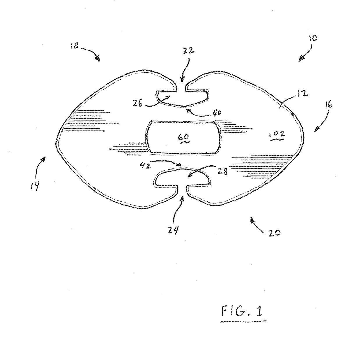
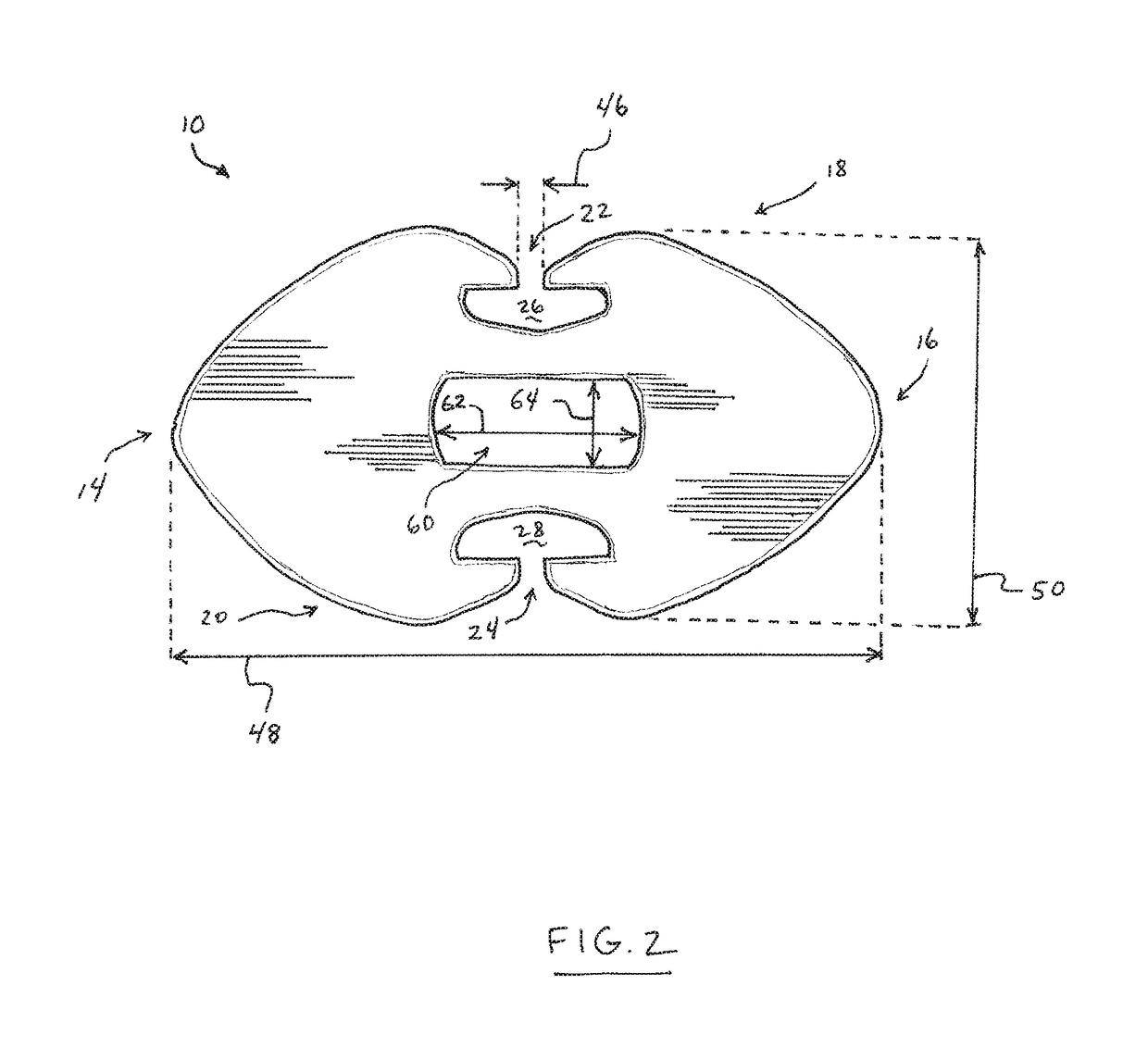
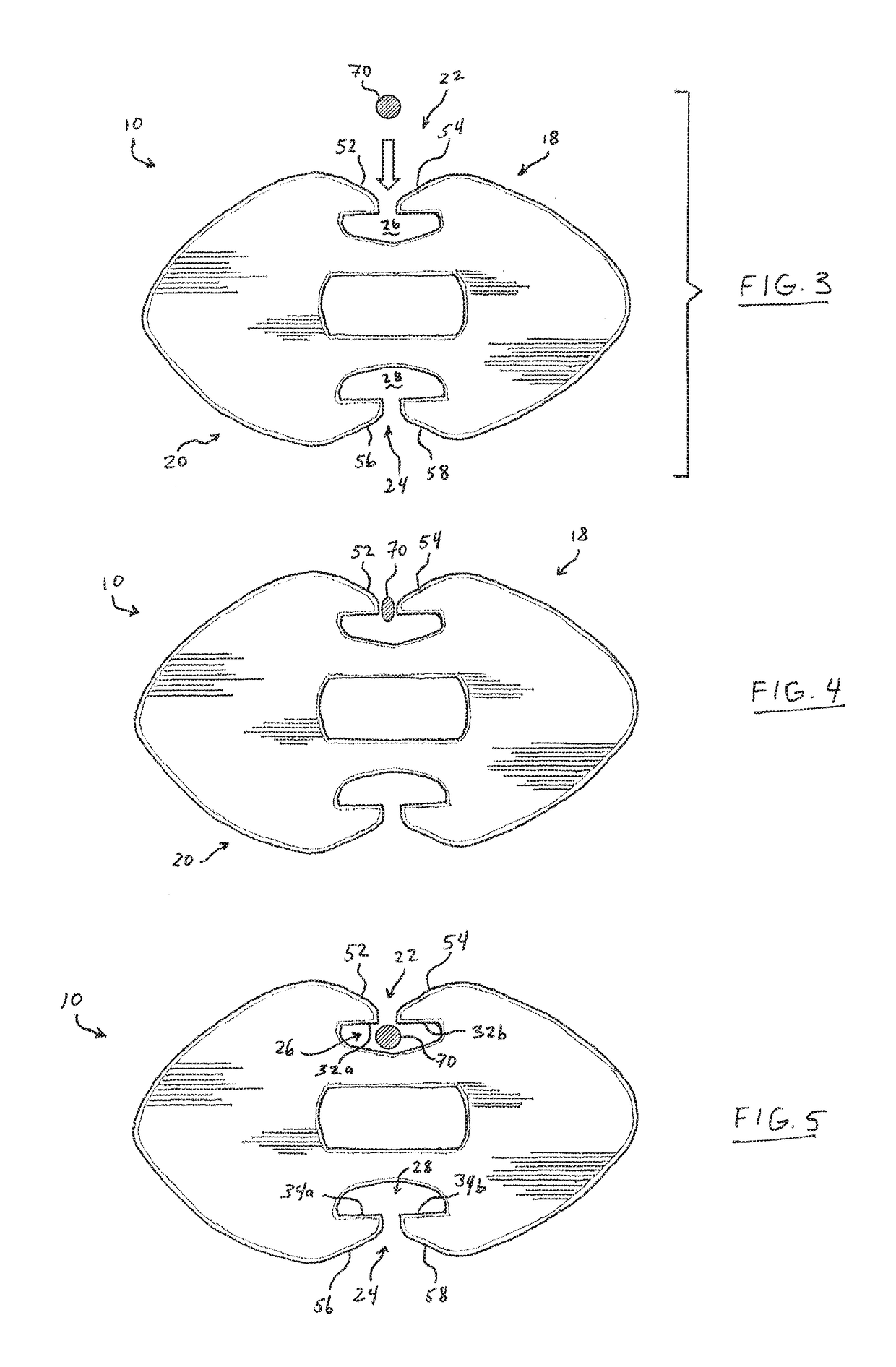
[0033]The present disclosure provides a suture button construct for use in surgical procedures. As shown in FIG. 1, suture button 10 is configured to be utilized in surgical procedures requiring a surgeon to pull one or more sutures tight, and to maintain a postoperative tension on the suture within a desired tensile range. Suture button 10 may be specifically configured in some embodiments to maintain suture tension following a repair of a root tear in...


PUM


Abstract

A suture button for a surgical procedure provides an anchor for pulling and maintaining suture tension through a transosseous tunnel during an operation such as meniscal root repair in the knee. The suture button includes a body having a first tapered longitudinal end, a second tapered longitudinal end, a first side, a second side, an anterior surface and a posterior surface. A first concave notch is defined in the first side, and a second concave notch is defined in the second side. The first notch is open to a first suture dock in the first side, and the second notch is open to a second suture dock in the second side. Each of the first and second suture docks includes a seat to centrally position suture material. A center passage is defined through the suture body at a location between the first and second suture docks.

Description

BACKGROUND[0001]The present invention relates generally to devices and methods for performing arthroscopic surgery on joints and more particularly to suture button devices and associated methods for anchoring and tensioning of sutures during and after surgery.[0002]Various types of sutures, suture fixation devices and associated methods are known in the art for securing a suture in a desired position and / or at a desired tension during and after surgical procedures. In many surgical procedures, a transosseous hole is drilled through a portion of bone, forming a rigid tunnel for passing a surgical instrument or a suture. The drilled tunnel includes a proximal opening adjacent a tissue repair site where a procedure for the repair of tissue is generally performed, such as but not limited to a procedure to repair a meniscus root tear in a knee. The drilled tunnel generally also includes a distal opening at a location remote from the repair site.[0003]During such procedures, one or more s...

Claims


Application Information

Patent Timeline
Patent Type & Authority Applications(United States)
IPC IPC(8): A61B17/04
CPCA61B17/0401A61B2017/0404A61B2017/0414A61B2017/0464A61B2017/0417A61B2017/0459A61B2017/0438
Inventor ANDERSON, CHRISTIAN N.
Owner ANDERSON CHRISTIAN N
Why Eureka
Try Eureka