
Three-dimensional posture estimating method and apparatus, device and computer storage medium

a posture estimation and three-dimensional technology, applied in image analysis, image enhancement, machine learning, etc., can solve the problem that images cannot be applied to all autonomous vehicle driving scenarios, and achieve the effect of facilitating mapping a detection resul

Active Publication Date: 2019-01-10
APOLLO INTELLIGENT DRIVING (BEIJING) TECHNOLOGY CO LTD
View PDF3 Cites 30 Cited by
  • Summary
  • Abstract
  • Description
  • Claims
  • Application Information

AI Technical Summary

Benefits of technology

The patent describes a method for mapping objects in a two-dimensional image to a three-dimensional space and determining their posture based on the object's size and the position of key points. This can be useful for things like autonomous driving. The technical effect is that it provides a more accurate and reliable way to map obstacles in a vehicle's environment and improve safety.

Problems solved by technology

However, due to lack of three-dimensional information, only a two-dimensional detection result on images cannot be applied to all autonomous vehicle driving scenarios.

Method used


Image

  • Three-dimensional posture estimating method and apparatus, device and computer storage medium
  • Three-dimensional posture estimating method and apparatus, device and computer storage medium
  • Three-dimensional posture estimating method and apparatus, device and computer storage medium

Examples


embodiment 1

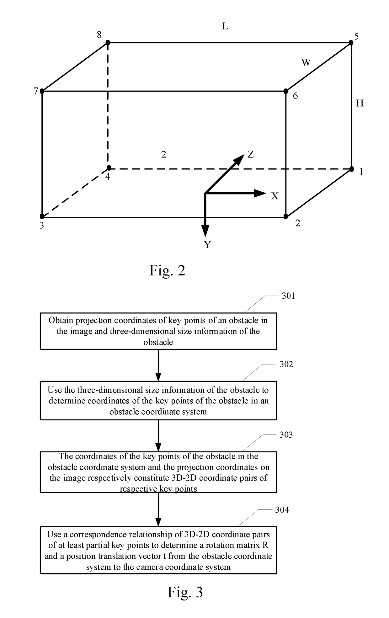
[0077]FIG. 3 is a flow chart of a method according to a first embodiment of the present disclosure. As shown in FIG. 3, the method may include the following steps:

[0078]301: obtaining projection coordinates of key points of an obstacle in the image and three-dimensional size information of the obstacle.

[0079]As far as the obstacle is concerned, an example is taken in which the eight apexes of the 3D enclosing box are considered as key points. The eight apexes have eight projection coordinates on the image, which may be respectively represented as qi, wherein i=1, 2, . . . , 8. The three-dimensional size information of the obstacle is reflected as length, width and height. In addition, it is possible to use a center point, a barycenter and the like of each plane of for example 3D enclosing box as key points.

[0080]In 302, the three-dimensional size information of the obstacle is used to determine coordinates of the key points of the obstacle in an obstacle coordinate system.

[0081]This...

embodiment 2

[0099]FIG. 4 is a flow chart of a method according to a second embodiment of the present disclosure. as shown in FIG. 4, the method may comprise the following steps:

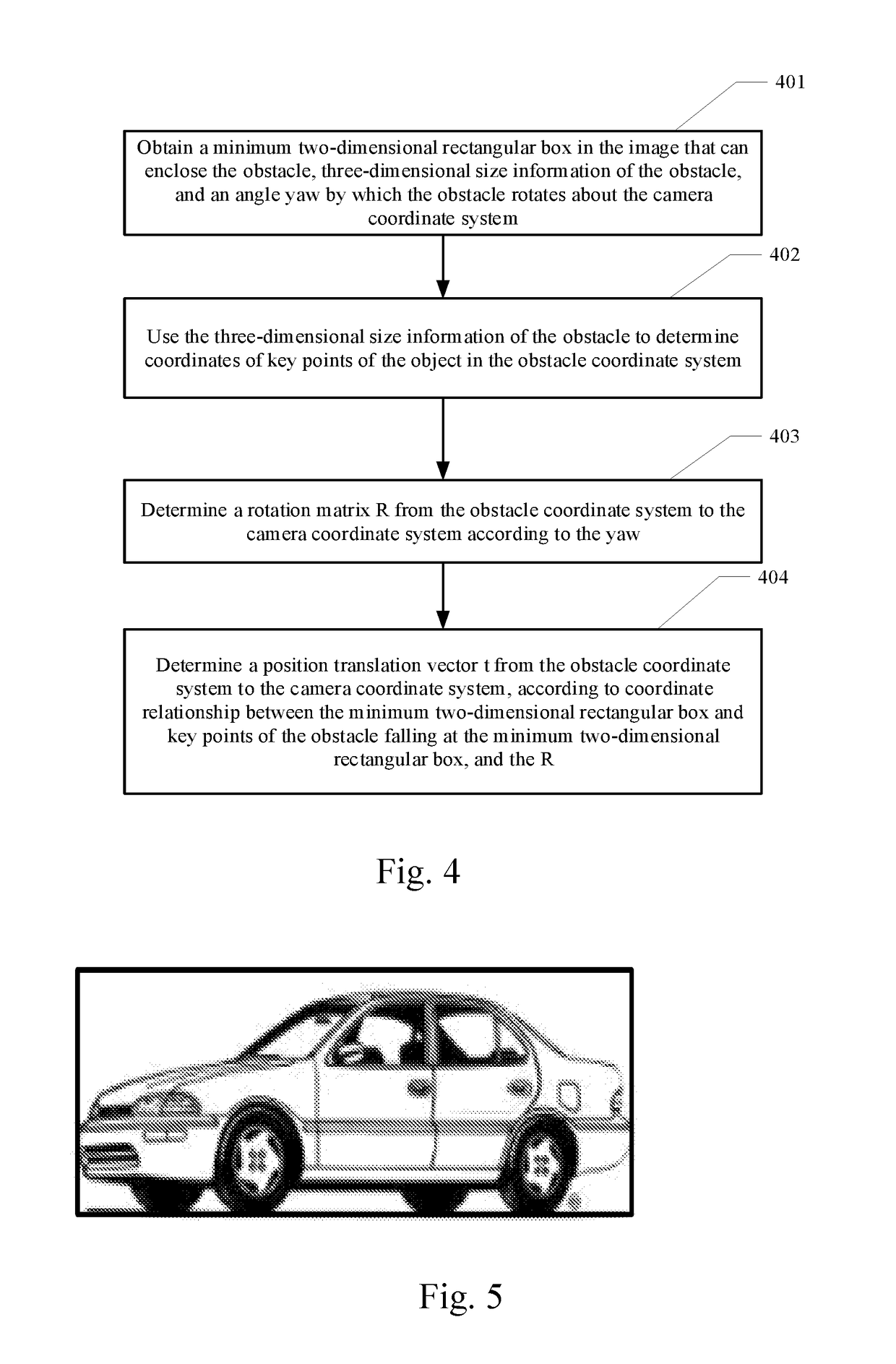
[0100]401 relates to obtaining a minimum two-dimensional rectangular box in the image that can enclose the obstacle, three-dimensional size information of the obstacle, and an angle yaw by which the obstacle rotates about the camera coordinate system.

[0101]For example, as shown in FIG. 5, the minimum two-dimensional rectangular box in the image that can enclose a vehicle is as shown by a black-line box in the figure.

[0102]The present embodiment is based on an assumption that the angle yaw by which the obstacle rotates about the camera coordinate system is known, wherein the manner of obtaining yaw may be based on a deep learning method, or employ other manners. This is not limited by the present disclosure.

[0103]402 relates to using the three-dimensional size information of the obstacle to determine coordinates of key po...


PUM


Abstract

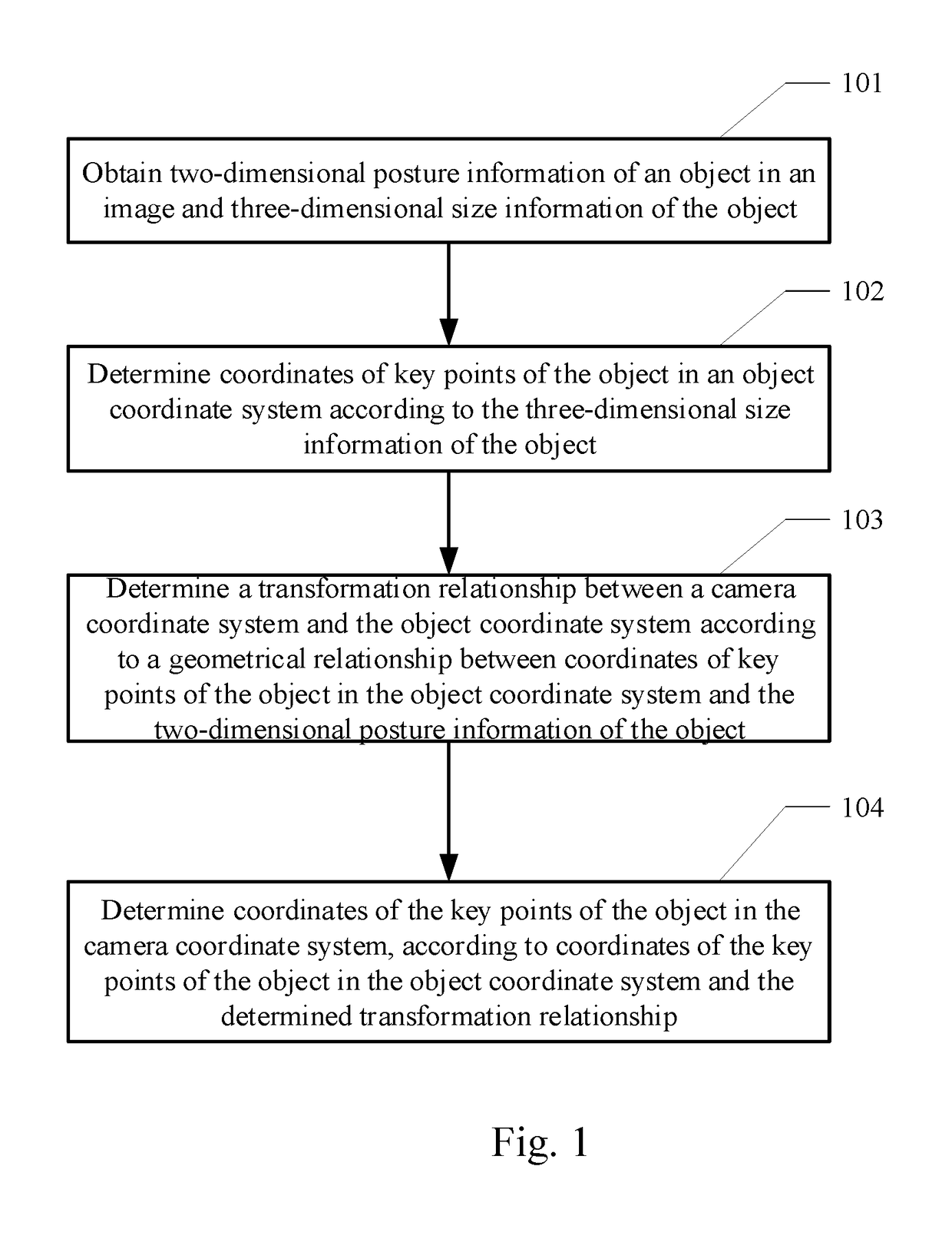
The present disclosure provides a three-dimensional posture estimating method and apparatus, a device and a computer storage medium, wherein the method comprises: obtaining two-dimensional posture information of an object in an image and three-dimensional size information of the object; determining coordinates of key points of the object in an object coordinate system according to the three-dimensional size information of the object; determining a transformation relationship between a camera coordinate system and the object coordinate system according to a geometrical relationship between coordinates of key points of the object in the object coordinate system and the two-dimensional posture information of the object. Application of this manner to the field of autonomous driving may implement mapping a detection result of a two-dimensional obstacle to a three-dimensional space to obtain its posture.

Description

[0001]The present application claims the priority of Chinese Patent Application No. 201710538045.8, filed on Jul. 4, 2017, with the title of “Three-dimensional posture estimating method and apparatus, device and computer storage medium”. The disclosure of the above applications is incorporated herein by reference in its entirety.FIELD OF THE DISCLOSURE[0002]The present disclosure relates to the technical field of computer application, and particularly to a three-dimensional posture estimating method and apparatus, a device and a computer storage medium.BACKGROUND OF THE DISCLOSURE[0003]In order to ensure safety of an autonomous vehicle traveling on a road, it is necessary to detect, in real time, three-dimensional location information of obstacles in a surrounding environment, and feed the three-dimensional location information back to a planning control system so as to perform avoiding operations. Currently, the technology of performing obstacle detection on images based on the dee...

Claims


Application Information

Patent Timeline
Patent Type & Authority Applications(United States)
IPC IPC(8): G06T7/73G06T7/60G06N7/00
CPCG06T7/75G06T7/60G06T2207/20081G06T2207/20108G06T2207/30252G06N7/005G06T7/73G06T3/08G06N20/00G06T2207/20084G06T2207/30261G06N7/01
Inventor SUN, XUNWANG, RUIZHAI, YUQIANGXIA, TIAN
Owner APOLLO INTELLIGENT DRIVING (BEIJING) TECHNOLOGY CO LTD
Learn More