System For Cooling A Cable

a cooling system and cable technology, applied in the direction of insulation conductors/cables, other domestic objects, transportation and packaging, etc., can solve the problems of line itself being stopped and the loss of the overall system productivity, and achieve the effect of easy and inexpensive manufacturing

Inactive Publication Date: 2019-01-10
SAMP CON UNICO SOCIO
View PDF3 Cites 5 Cited by
  • Summary
  • Abstract
  • Description
  • Claims
  • Application Information

AI Technical Summary

Benefits of technology

[0011]So, the main object of the present invention is to provide a system for cooling a cable, which is free from the drawbacks described above and, at the same time, is easy and inexpensive to manufacture.

Problems solved by technology

However, the current systems, while ultimately ensuring high productivity, have the following drawbacks:the cooling of the cable is substantially fixed;the management of the multi-pass apparatus is delegated to a sensor device that does not always guarantee adequate accuracy; andwhen the spool must be changed downstream of the cooling system, the line itself must be stopped, with a consequent loss of productivity of the overall system.

Method used


Image

  • System For Cooling A Cable
  • System For Cooling A Cable
  • System For Cooling A Cable

Examples


Embodiment Construction

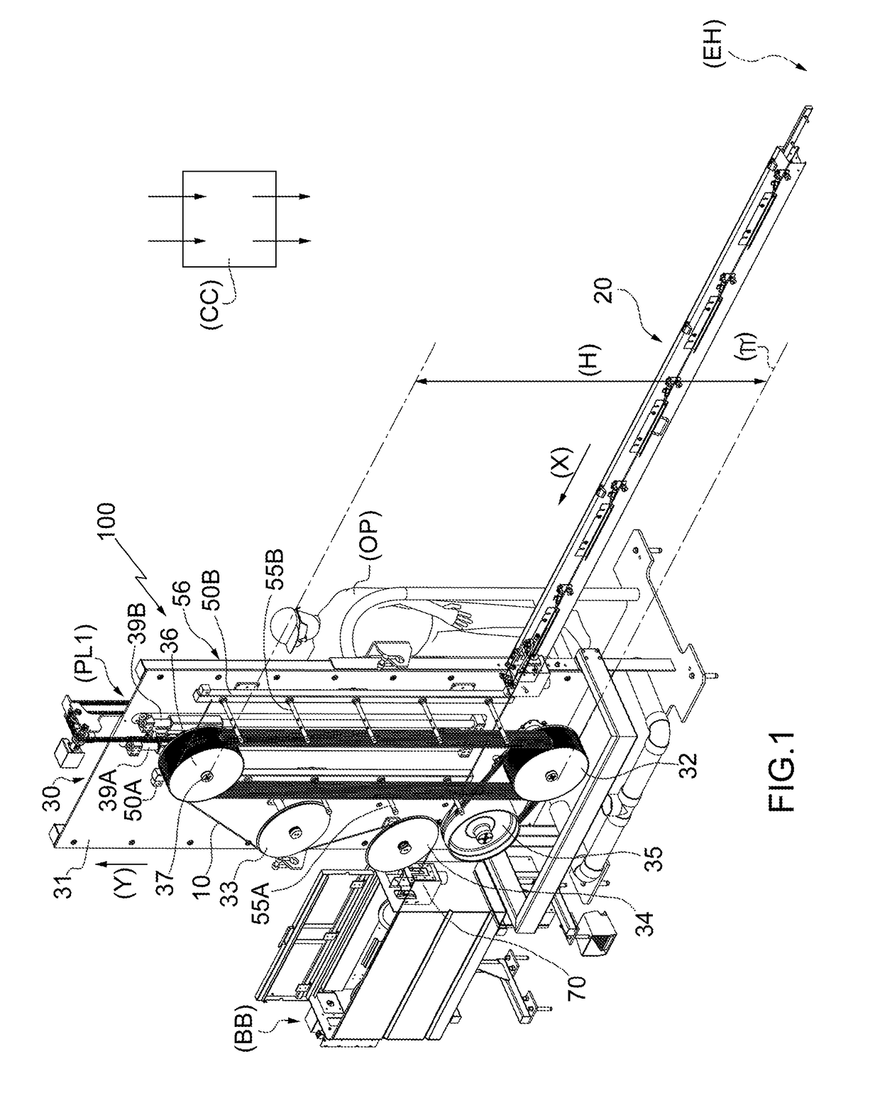
[0018]In FIG. 1, the numeral 100 indicates as a whole a system for cooling a cable 10 manufactured according to the specifications of the present invention.

[0019]The cooling system 100 for cooling the cable 10 (for example, made of PVC-coated copper) is located between an extrusion head (EH) and a winding machine (BB).

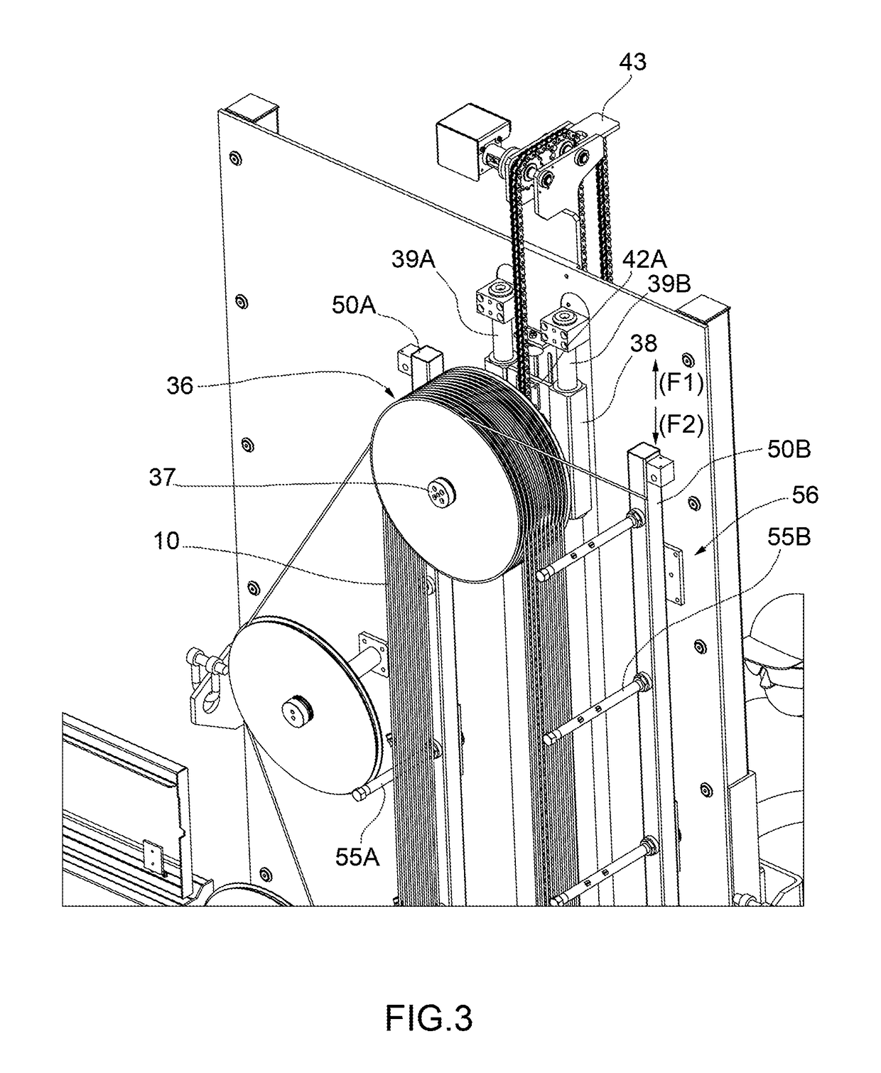
[0020]The cooling system 100 further comprises a fixed cooling channel 20 of a known type, which therefore will not be described in detail, and a multi-pass apparatus 30, that, in the embodiment illustrated in the attached figures, extends along a vertical axis with respect to the forward movement direction of the cable 10.

[0021]In other words, if the cable 10 in the channel 20 lies substantially along a first horizontal axis (X), the multi-pass apparatus 30, in this specific case, extends along a second vertical axis (Y), perpendicular to the first axis (X).

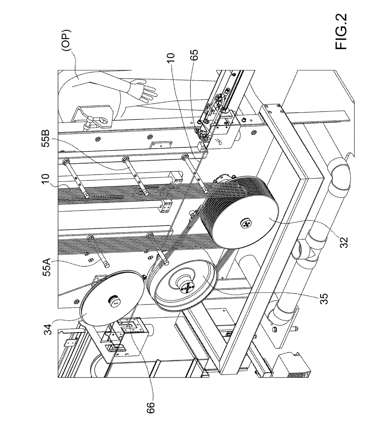
[0022]The multi-pass apparatus 30 comprises a frame 31 which supports three fixed pulleys 32, 33, 34, and a fixe...


PUM

PropertyMeasurementUnit
speedaaaaaaaaaa
lengthaaaaaaaaaa
tensionaaaaaaaaaa

Abstract

A cooling system (100) for cooling a cable (10). The system (100) comprises: —at least one fixed cooling channel (20), which is arranged downstream of an extrusion head (EH); and —at least one multi-pass apparatus (30), which in turn comprises a set of fixed pulleys (32, 33, 34), and a fixed, motor-driven capstan (35) designed to wind the cable (10). The system (100) is characterized in that the multi-pass apparatus (30) comprises a movable pulley (36) designed to translate along vertical guides (39A, 39B). The movable pulley (36) and the vertical guides (39A, 39B) are contained in a cooling device (56) for cooling the cable (10).

Description

TECHNICAL FIELD[0001]The present invention relates to a system for cooling a cable.[0002]In particular, the present invention finds advantageous, but not exclusive, application in the cooling of an electrical cable, to which the following description will make explicit reference without thereby losing generality.BACKGROUND ART[0003]As is known, current systems for the cooling of cables comprise the following devices arranged in series:[0004]at least one fixed cooling channel downstream of the extrusion head; and[0005]a (normally horizontal) multi-pass apparatus comprising a set of fixed pulleys, and a fixed, motor-driven capstan.[0006]In addition, with regard to a traditional system, the cooling length of the cable, as well as the cable accumulation in the multi-pass apparatus, are fixed; moreover, the tensioning of the cable downstream of the multi-pass apparatus is controlled by a sensor device.[0007]However, the current systems, while ultimately ensuring high productivity, have t...

Claims


Application Information

Patent Timeline
Patent Type & Authority Applications(United States)
IPC IPC(8): H01B13/14B29C47/00B29C47/02B29C47/88B65H54/22B65H67/04B65H71/00B29C48/05B29C48/154
CPCH01B13/145B29C47/0014B29C47/025B29C47/8815B29L2031/3462B65H67/0405B65H71/00B29K2705/10B29K2027/06B65H54/22B29C48/05B29C48/154B29C48/911
Inventor GUMINA, ANTONIOBALESTRINO, DANIELE
Owner SAMP CON UNICO SOCIO
Why Eureka
Try Eureka