Control module for a constant-frequency switching converter and method for controlling a switching converter

a control module and converter technology, applied in the direction of electric variable regulation, efficient power electronics conversion, electric vehicles, etc., can solve the problems of converter operating in a region of low efficiency, high variability of switching frequency, and high total harmonic distortion (thd) of input current that is relatively high

Active Publication Date: 2019-01-10
STMICROELECTRONICS SRL
View PDF0 Cites 39 Cited by
  • Summary
  • Abstract
  • Description
  • Claims
  • Application Information

AI Technical Summary

Benefits of technology

[0013]According to at least one embodiment of the present disclosure, a control module controls a switching converter configured to generate an output electrical quantity from an input electrical quantity and including an inductor element and one switching element, which is operable in such a manner as to vary a current flowing in the inductor element. The control module includes:
[0014]a driver circuit configured to generate a control signal designed to control on and off cycles of the switching element;
[0015]a first modulation circuit configured to generate first edges of a first type of a control signal as a function of the input electrical quantity and of a reference electrical quantity, and configured to control the driver circuit with the first edges of the control signal; and
[0016]a second modulation circuit configured to generate second edges of a second type of the control signal and configured to control the driver circuit with the second edges of the control signal.

Problems solved by technology

Unfortunately, the CCM converters with fixed off-time control are also characterized by a few disadvantages, which include, amongst others, a total harmonic distortion (THD) of the input current that is relatively high and a high variability of the switching frequency.
In particular, as far as the high variability of the switching frequency is concerned, this is undesirable since it includes the fact that, over certain periods of time, the switching frequency takes particularly high values, and thus the converter operates in a region of low efficiency.

Method used


Image

  • Control module for a constant-frequency switching converter and method for controlling a switching converter
  • Control module for a constant-frequency switching converter and method for controlling a switching converter
  • Control module for a constant-frequency switching converter and method for controlling a switching converter

Examples


Embodiment Construction

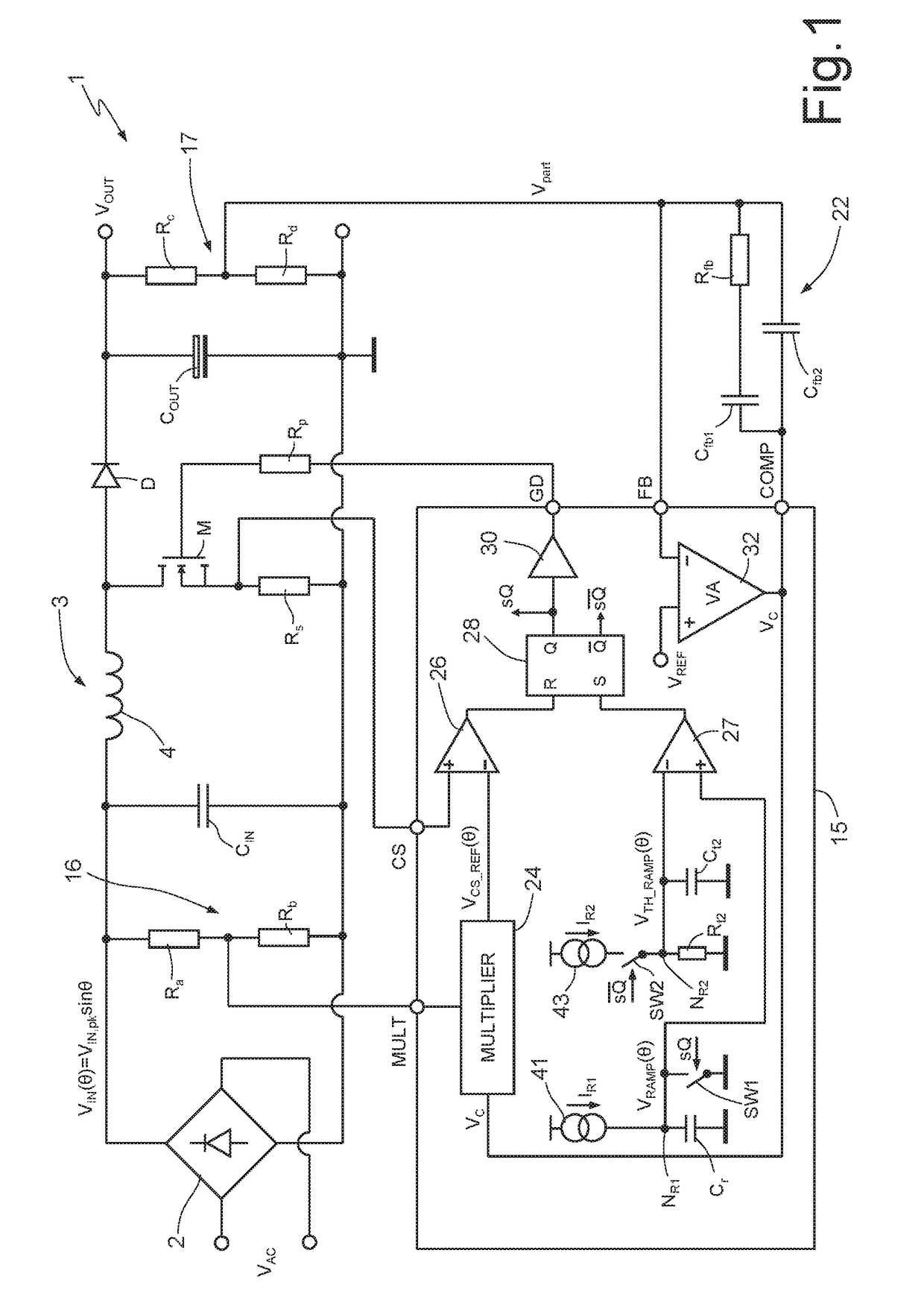
[0028]FIG. 1 shows a switching power supply 1 of the boost type, which is referred to hereinafter as boost power supply 1.

[0029]In more detail, the boost power supply 1 includes a bridge rectifier 2, which has two input terminals, designed to receive an alternating voltage VAC from a supply line, and a first and a second output terminal, respectively connected to ground and to a first terminal of a filtering capacitor Cin, whose second terminal is connected to ground. The bridge rectifier 2 supplies, on its second output terminal, a voltage VIN(θ) which is referred to hereinafter as input voltage VIN(θ); θ is the phase of the alternating voltage VAC present on the power supply line, therefore the relationship VIN(θ)=VIN,pk*sin θ is valid, in which VIN,pk indicates the peak voltage of the input voltage VIN(θ) and 0≤θ<π.

[0030]The boost power supply 1 furthermore comprises a boost converter 3, which includes, aside from the filtering capacitor Cin, an inductor 4, a control module 15, a...


PUM


Abstract

A control module controls a switching converter including at least one inductor element and one switching element. The module includes: a driver circuit that generates a control signal which controls the on and off cycles of the switching element; a first modulation circuit which sends a command to the driver circuit in such a manner as to generate edges of a first type of the control signal, as a function of the input electrical quantity and of a reference electrical quantity; and a second modulation circuit which sends a command to the driver circuit in such a manner as to generate edges of a second type of the control signal, as a function of a first and a second internal electrical quantity, which are functions respectively of the charges on a first and a second capacitor, which are charged and discharged as a function of the control signal.

Description

BACKGROUNDTechnical Field[0001]The present disclosure relates to a control module for a switching converter, which has a constant switching frequency. Furthermore, the present disclosure refers to a method for controlling a switching converter.Description of the Related Art[0002]As is known, there exist various types of switching converters, amongst which “flyback”, “boost” and “buck” converters may, for example, be mentioned.[0003]Switching converters are for example employed for correcting the power factor (PF), namely circuits designed to increase the power factor, which, as is known, is indicative of the ratio between the real power and the apparent power at the input to a load.[0004]Referring, by way of example, to a switching converter of the boost type, it is known that this typically includes at least one inductor, whose charging and discharging phases are controlled in a cyclical manner via a MOSFET transistor coupled to it, in such a manner as to allow the converter to gen...

Claims


Application Information

Patent Timeline
Patent Type & Authority Applications(United States)
IPC IPC(8): H02M3/157H02M3/335H02M3/158H02J7/00
CPCH02M3/156H02M3/157H02M3/33515H02J7/008H02M3/1582H02M3/1584H02M1/4225H02M1/12Y02B70/10
Inventor GRITTI, GIOVANNI
Owner STMICROELECTRONICS SRL
Why Eureka
Try Eureka