Airflow straightener in an electronics chassis

a technology of airflow and electronics chassis, which is applied in the direction of cooling/ventilation/heating modifications, instruments, computing, etc., can solve the problems of non-uniform swirling air mixing prior to entering the card cage area, electrical devices that generate excess heat, and parts of the module may be difficult to cool sufficiently, etc., to achieve the effect of difficult to cool sufficiently

Active Publication Date: 2019-01-10
NATIONAL INSTRUMENTS
View PDF2 Cites 1 Cited by
  • Summary
  • Abstract
  • Description
  • Claims
  • Application Information

AI Technical Summary

Benefits of technology

[0003]Instruments for collecting data or information from an environment or unit under test may be coupled to and controlled by computer systems. Data collected by these instruments may be used to control units being tested (e.g., an overheated unit may be shutdown) or an environment (e.g., ventilation systems may be activated if a certain chemical is detected in the air). Instrumentation systems such as those described above may run on a platform such as Peripheral Component Interconnect (PCI) eXtensions for Instrumentation (PXI). PXI may combine a high-speed PCI bus with integrated timing and triggering features designed for measurement and automation applications to deliver performance improvements over other architectures. PCI or PXI devices may be comprised of modules which may be grouped together as modules in a chassis in some embodiments. However, due to the compact design of these modules, parts of the module may be difficult to cool sufficiently.

Problems solved by technology

Some electronic devices generate excess heat in the course of their operation.
Delivering adequate cooling air flow to each electronic device in a chassis may be an important issue for the proper functioning, lifetime, or other characteristics of electronic devices contained in a chassis.
However, due to the compact design of these modules, parts of the module may be difficult to cool sufficiently.
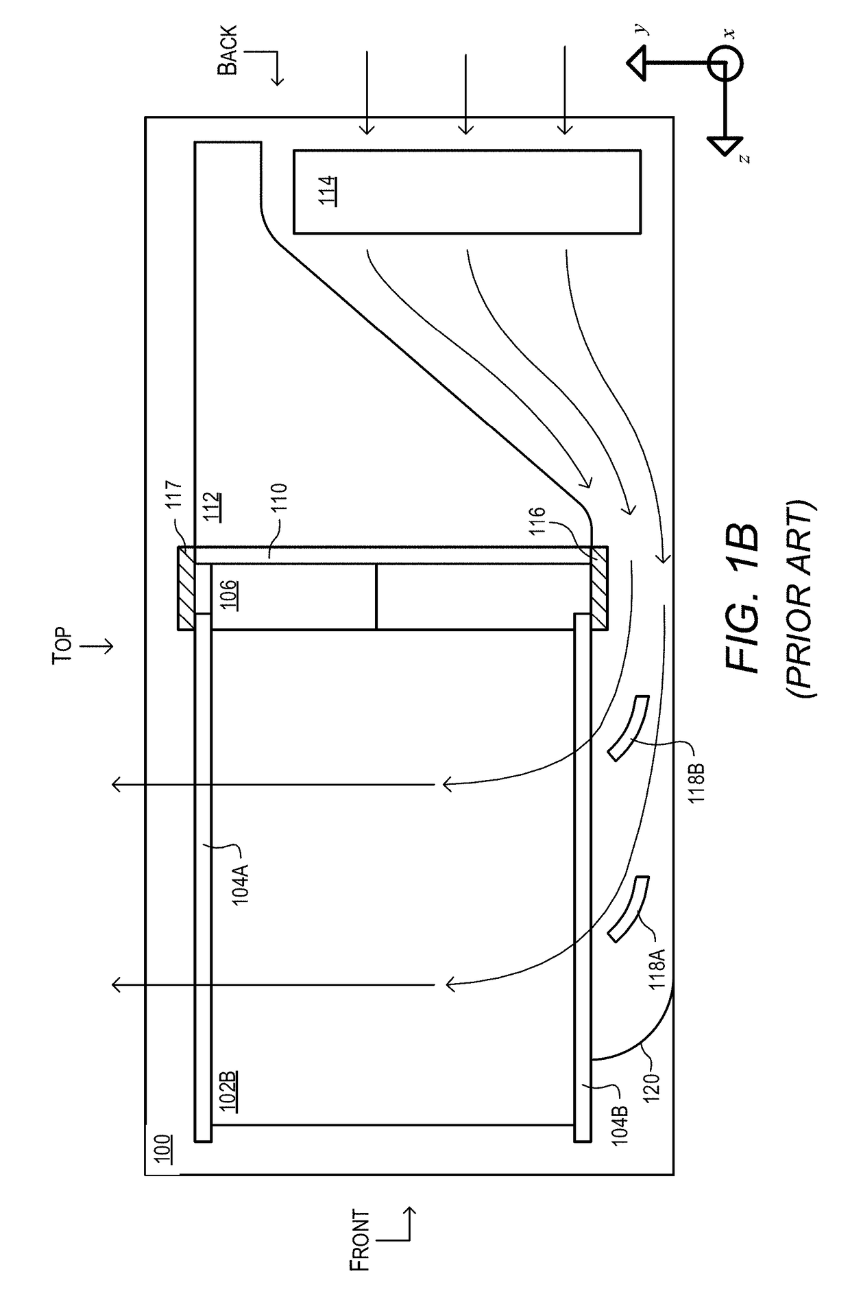
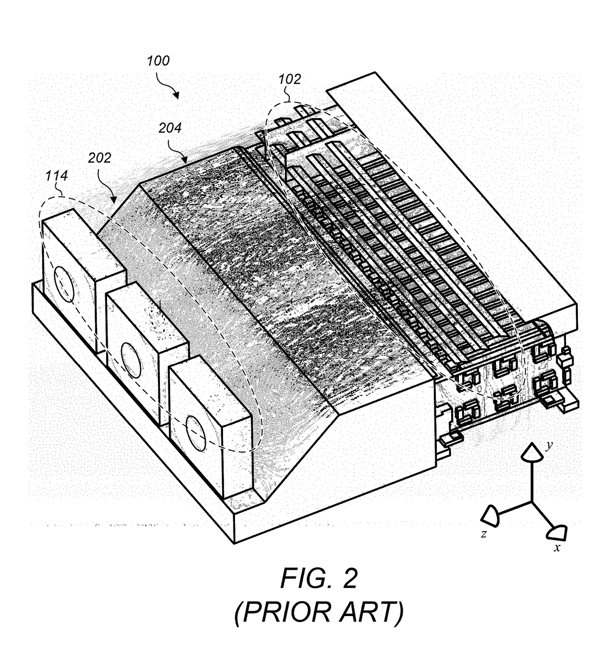
In these embodiments, the swirling air mixes prior to entering the card cage area in a non-uniform manner due to 3-dimensional mixing of the air.
This non-uniform air flow pattern may provide some slots with more cooling than others and non-uniform cooling within each slot.

Method used


Image

  • Airflow straightener in an electronics chassis
  • Airflow straightener in an electronics chassis
  • Airflow straightener in an electronics chassis

Examples


Embodiment Construction

[0027]Instruments for collecting data or information from an environment or unit under test may be coupled to and controlled by computer systems. Data collected by these instruments may be used to control units being tested (e.g., an overheated unit may be shutdown) or an environment (e.g., ventilation systems may be activated if a certain chemical is detected in the air). Data may also be displayed to a user for control and / or experimental purposes (e.g., to improve the design of the unit being tested). Instruments and / or computer systems may also perform various data analysis and data processing on acquired data prior to control of the unit and / or display of the data to the user. Examples of various types of instruments include oscilloscopes, digital multimeters, pressure sensors, etc., and the types of information that might be collected by respective instruments include voltage, resistance, distance, velocity, pressure, oscillation frequency, humidity or temperature, among other...


PUM


Abstract

Various types of electronic devices may be mounted in a chassis in order to facilitate interfacing with the devices, containing the devices, provide cooling systems which may remove heat from the electronic devices, etc. Delivering adequate cooling air flow to each electronic device in a chassis may be an important issue for the proper functioning, lifetime, or other characteristics of electronic devices contained in a chassis. Embodiments presented herein describe a novel design for an air flow straightener that is configured for insertion within the chassis to straighten the airflow. In some embodiments, the grating is comprised of long dividers and shorter dividers that are predominantly oriented perpendicularly to each other, resulting in a rectangular grating. Including such a grating in a chassis may improve the uniformity and performance of the cooling system.

Description

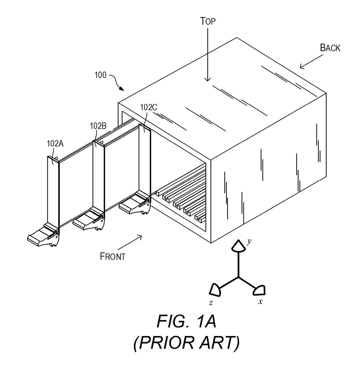
BACKGROUNDTechnical Field[0001]The present invention relates generally to mechanisms for cooling electronic circuit boards, and more particularly, to the cooling of components by air flow generated by fans.Description of the Related Art[0002]Various types of electronic devices may be mounted in a chassis in order to facilitate interfacing with the devices, containing the devices, managing the devices, or other reasons. Some electronic devices generate excess heat in the course of their operation. In some embodiments, a chassis includes cooling systems which may remove heat from the electronic devices. An example of a cooling system is a fan or set of fans which may be configured to move air through or across the electronic devices. Delivering adequate cooling air flow to each electronic device in a chassis may be an important issue for the proper functioning, lifetime, or other characteristics of electronic devices contained in a chassis. As such, improvements in the field of contro...

Claims


Application Information

Patent Timeline
Patent Type & Authority Applications(United States)
IPC IPC(8): H05K7/20G06F1/20
CPCH05K7/20145G06F1/20H05K7/20727
Inventor BALDWIN, JR., RICHARD G.HARLAN, JARED S.TOTH, D. VANCE
Owner NATIONAL INSTRUMENTS
Why Eureka
Try Eureka