Piping connection device and heat pump cycle device having same

a technology of connection device and heat pump cycle, which is applied in the direction of service pipe system, pipe coupling, pipe coupling, etc., can solve the problems of deformation or damage of the respective portion, and damage to the member may be limited, so as to achieve slow temperature drop speed, limited damage to the member, and high heat capacity

Inactive Publication Date: 2017-02-14
DENSO CORP
View PDF20 Cites 1 Cited by
  • Summary
  • Abstract
  • Description
  • Claims
  • Application Information

AI Technical Summary

Benefits of technology

[0006]However, in the above pipe connecting structure, moisture entering and adhering between those members may be cooled and frozen, and those members may be damaged by volume expansion of ice. As a related art that copes with freezing, techniques disclosed in, for example, Patent Document 1 and Patent Document 2 have been known. According to Patent Document 1, in a refrigeration cycle, if a given condition is satisfied, an exterior heat exchanger switches to an operating state functioning as a radiator, to thereby limit frosting of the exterior heat exchanger. Also, according to Patent Document 2, in a solenoid valve integrated expansion valve, a heat transfer member that transfers a heat generated in an electromagnetic coil of an electromagnetic valve to a valve main body is provided to limit the freezing of a valve main body surface.
[0007]The present disclosure has been made in view of the above, and an object of the present disclosure is to provide a piping connection device that can limit a damage to members which is caused by freezing of water entering between the members, and a heat pump cycle device having the piping connection device.
[0009]According to the above configuration, for example, water generated in a gap between the female block member and the first pipe can be escaped to the drain passage, and discharged from the gap. With the above configuration, deforming or damaging of the respective portions can be limited. The deforming or damaging is caused by a fact that the water generated in the gap between the female block member and the first pipe is frozen with a reduction in fluid temperature, and subjected to volume expansion to push out the gap, or caused by repetition of the freezing. With the above configuration, according to the present disclosure, the piping connection device can be provided, which is capable of limiting the damage to the members caused by freezing water penetrated between the members.
[0011]According to the above configuration, the portion in which the drain passage is provided is higher in the heat capacity in the female block member. For that reason, when the fluid temperature is lowered, the female block member is frozen in order of heat capacity from low to high. The drain passage is hardly cooled in the female block member, and a speed of the temperature decrease is slow. For that reason, even if water escaped from the gap between the female block member and the first pipe dwells in the drain passage, the freeze of dwelling water is delayed or dwelling water is not frozen. Thus, the damage to the member can be limited. With the above configuration, according to the present disclosure, the piping connection device can be provided, which is capable of limiting the damage to the members caused by freezing water penetrated between the members.

Problems solved by technology

However, in the above pipe connecting structure, moisture entering and adhering between those members may be cooled and frozen, and those members may be damaged by volume expansion of ice.
With the above configuration, deforming or damaging of the respective portions can be limited.
The deforming or damaging is caused by a fact that the water generated in the gap between the female block member and the first pipe is frozen with a reduction in fluid temperature, and subjected to volume expansion to push out the gap, or caused by repetition of the freezing.

Method used


Image

  • Piping connection device and heat pump cycle device having same
  • Piping connection device and heat pump cycle device having same
  • Piping connection device and heat pump cycle device having same

Examples


first embodiment

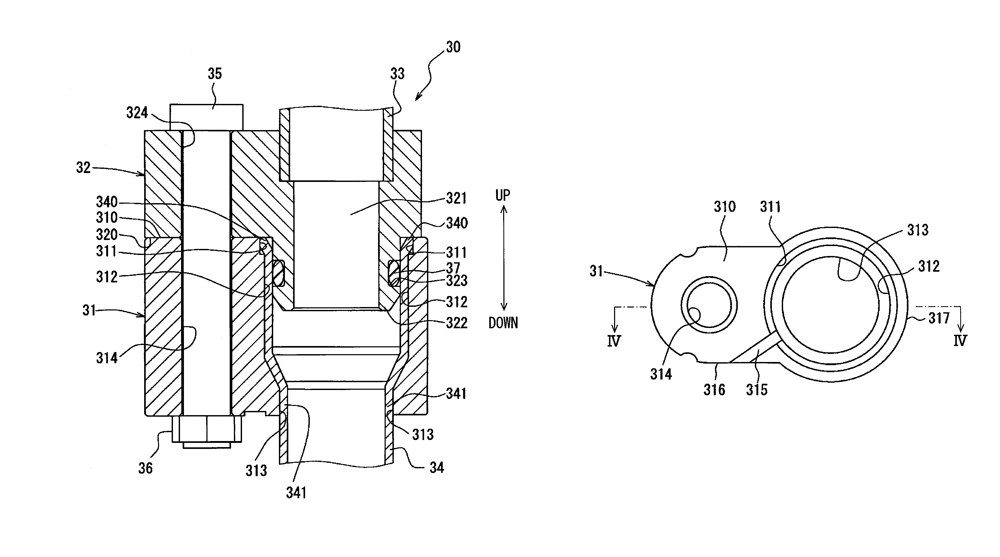
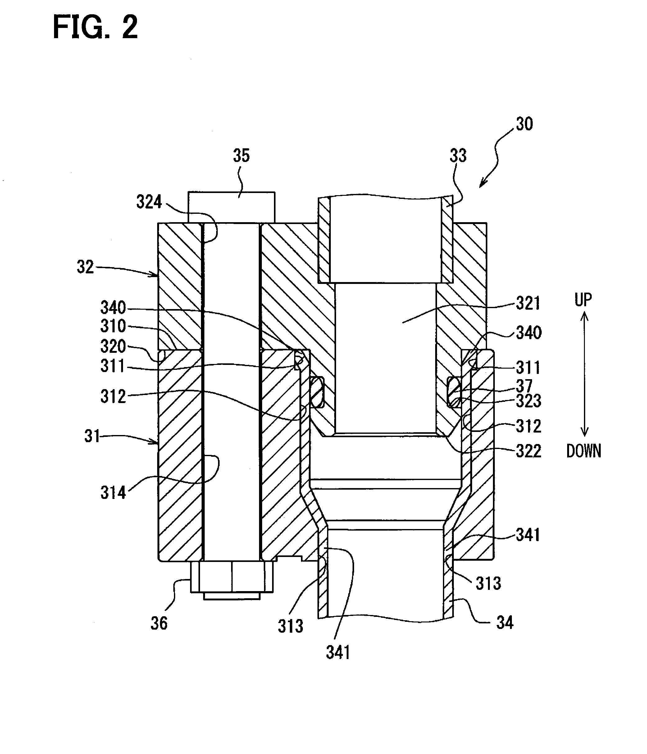
[0027]A piping connection device according to the present disclosure is configured to connect respective pipes into which fluid flows to each other. The respective pipes are fixed in a state where the respective pipes are inserted into block members each presenting a lump of a given shape, and those two block members are combined together in a given state, and fixed, as a result of which the pipes internally communicate with each other so that the fluid smoothly flows in the pipes. The fluid that flows in the pipe can be lowered in temperature according to operating conditions or use environments such as water, refrigerant, or various gases. For example, if the fluid is refrigerant, the piping connection device according to the present disclosure is used as a device that connects respective refrigerant pipes used in a cycle in which the refrigerant flows, such as a refrigerator vehicle, a vehicle air conditioning system, or a water heater.

[0028]A first embodiment which is one embodi...

second embodiment

[0072]In a second embodiment, a piping connection device according to another configuration to the first embodiment will be described with reference to FIGS. 6 to 8. In FIGS. 6 to 8, components denoted by the same symbols as those referred to in the first embodiment represent identical components, and their operational advantages are also identical with those in the first embodiment. Hereinafter, a description will be given of a configuration, a processing procedure, and operation different from those in the first embodiment.

[0073]The piping connection device according to the second embodiment is characterized in a drain passage 315A formed in a female block member 31A. The drain passage 315A is a passage through which an internal passage located inside of the small-diameter hole portion 313 communicates with the other outer surface 316. Therefore, the drain passage 315A is a passage through which a part of the outer peripheral surface of the first pipe 34 communicates with the othe...

third embodiment

[0075]In a third embodiment, a description will be given of another configuration in which the drain passages 315 and 315A described in the first and second embodiments described above are disposed in arbitrary places in the female block members 31 and 31A regardless of the above-mentioned area with reference to FIGS. 9 to 11. Hereinafter, a description will be given of the configuration and operation different from those in the above respective embodiments. Therefore, the configuration and operation not particularly described are identical with those described in the above respective embodiments.

[0076]A drain passage 415 has a passage transverse area, for example, a lower value of a passage diameter determined according to a position in a female block member 41. In other words, the passage transverse area of the drain passage 415 is set on the basis of a position of the drain passage 415 angularly displaced around the axial center of the first pipe 34 with a thinnest portion as a s...


PUM


Abstract

A piping connection device includes a female block member fixed integrally with a male block member, and a first pipe is inserted into the female block member. The piping connection device further includes a drain passage through which a part of an outer peripheral surface of the first pipe communicates with an outer surface of the female block member. The drain passage is disposed in a portion higher in heat capacity than the other portions in the female block member.

Description

CROSS REFERENCE TO RELATED APPLICATIONS[0001]This application is a U.S. National Phase Application under 35 U.S.C. 371 of International Application No. PCT / JP2013 / 003658 filed on Jun. 11, 2013 and published in Japanese as WO 2013 / 190803 A1 on Dec. 27, 2013. This application is based on and claims the benefit of priority from Japanese Patent Applications No. 2012-141197 filed on Jun. 22, 2012, and No. 2013-110165 filed on May 24, 2013. The entire disclosures of all of the above applications are incorporated herein by reference.TECHNICAL FIELD[0002]The present disclosure relates to a piping connection device that connects block members to which pipes are connected, and a heat pump cycle device having the piping connection device.BACKGROUND ART[0003]A pipe connecting structure known up to now couples two pipes together by connecting a block member, to which one pipe is fixed, to a block member, to which another pipe is fixed, by a fastening device.PRIOR ART DOCUMENTPatent Document[0004...

Claims


Application Information

Patent Timeline
Patent Type & Authority Patents(United States)
IPC IPC(8): F16L55/00B60H1/00F16L41/08F16L23/032F16L23/00F16L21/08F16L21/04F16L23/036F16L19/00E03B7/12
CPCF16L21/08B60H1/00571F16L19/00F16L21/04F16L23/003F16L23/032F16L23/036F16L41/086E03B7/12F16L2201/40
Inventor OKADA, KEIHIGUCHI, TERUKAZUNAGANUMA, SHINICHIYANAGIMACHI, YOSHINORI
Owner DENSO CORP
Why Eureka
Try Eureka