Air conditioner for vehicle

a technology for air conditioners and vehicles, applied in the direction of domestic cooling devices, lighting and heating devices, cooling fluid circulation, etc., can solve the problems of easy frosting of uniform flow-speed distribution of air flowing through the evaporator, etc., to achieve the effect of reducing the flow speed of air flowing through the passenger seat side part of the evaporator and intensive air conditioning operation

Inactive Publication Date: 2014-12-25
DENSO CORP
View PDF6 Cites 17 Cited by
  • Summary
  • Abstract
  • Description
  • Claims
  • Application Information

AI Technical Summary

Benefits of technology

[0005]However, according to investigations of inventors of the present application, a flow-speed distribution of air flowing through the evaporator may easily become un-uniform when the passenger-seat-side air outlet is closed so as to perform the air conditioning operation intensively around the driver seat. For example, in a normal air-conditioning operation, air flowing through mainly a driver-seat-side part of the evaporator is guided to flow toward the driver-seat-side air outlet, and air flowing through mainly a passenger-s

Problems solved by technology

However, according to investigations of inventors of the present application, a flow-speed distribution of air flowing through the evaporator may easily become un-uniform when the passenger-seat-side air outlet is closed so as to perform the air conditioning operation intensive

Method used


Image

  • Air conditioner for vehicle
  • Air conditioner for vehicle
  • Air conditioner for vehicle

Examples


first embodiment

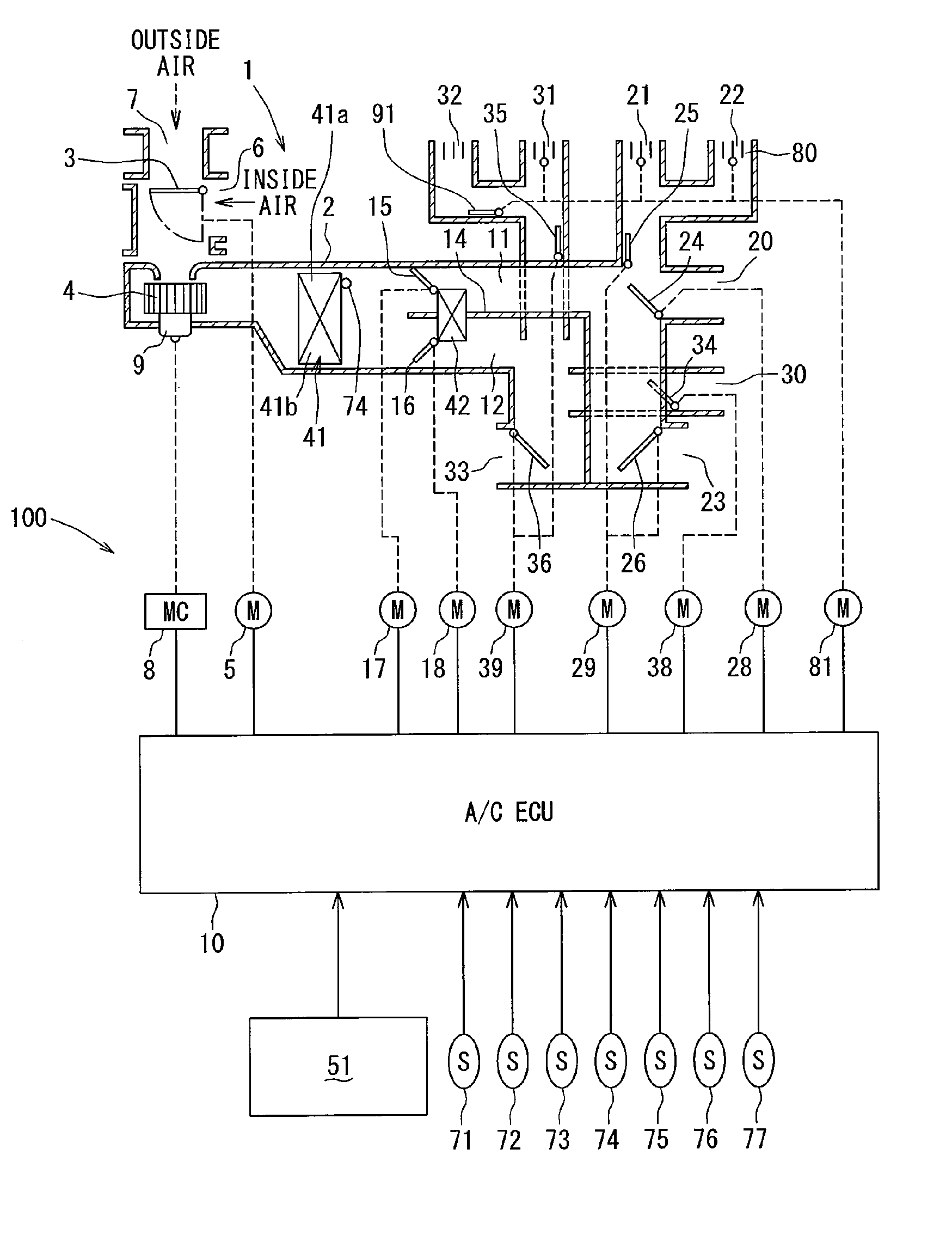
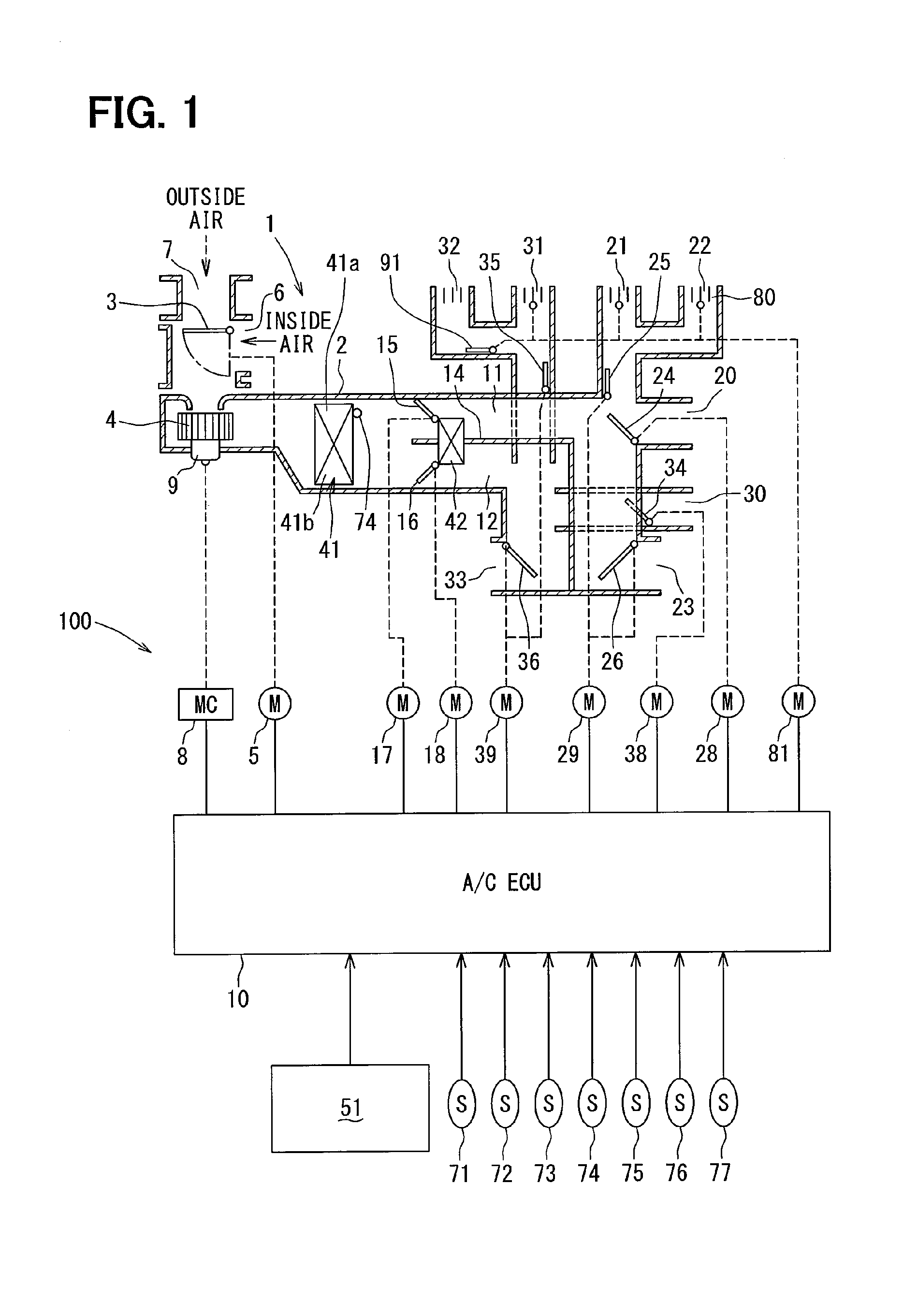
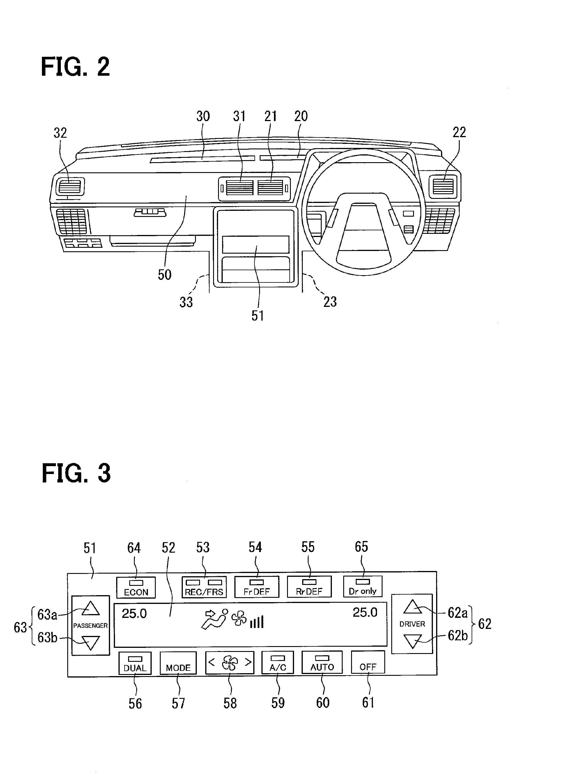
[0030]A first embodiment of the present disclosure will be described below referring to FIGS. 1-9. FIG. 1 is a schematic diagram illustrating a configuration of an air conditioner 100 for a vehicle of the first embodiment. FIG. 2 is a front view of an instrument panel 50 to which the air conditioner 100 is disposed and shows locations of air outlets for front seats. FIG. 3 is a front view of an air-conditioning operating panel 51.

[0031]The air conditioner 100 is an automatic air conditioning system for a vehicle, for example, a vehicle mounting a water-cooled engine for driving. In the air conditioner 100, an air conditioning unit 1 performing air conditioning operation in a passenger compartment of the vehicle is controlled by an air-conditioning electrical control unit (i.e., an air-conditioning ECU) 10.

[0032]The air conditioning unit 1 is a left / right independent type air conditioning unit capable of (i) independently regulating temperature of a driver-seat-side area to be air co...


PUM


Abstract

In an air conditioner for a vehicle, a flow speed of air flowing through a first ventilation part of an evaporator is faster than a flow speed of air flowing through a second ventilation part of the evaporator when an intensive air-conditioning operation for a driver seat is operated, with respect to a case where a normal air-conditioning operation is performed. In this case, a correct target evaporator temperature is calculated to be higher by a predetermined temperature than a target evaporator temperature, and a detected temperature detected by an evaporator sensor is approached to the correct target evaporator temperature. Therefore, it can restrict the second ventilation part from being frosted.

Description

CROSS REFERENCE TO RELATED APPLICATION[0001]This application is based on Japanese Patent Applications No. 2011-274953 filed on Dec. 15, 2011, the contents of which are incorporated herein by reference in its entirety.FIELD OF THE INVENTION[0002]The present disclosure relates to an air conditioner for a vehicle, in which air is cooled at a cooling heat exchanger and blown into a passenger compartment of the vehicle.BACKGROUND OF THE INVENTION[0003]Conventionally, Patent Document 1 discloses an air conditioner for a vehicle. In the air conditioner for a vehicle, conditioned air, of which temperature is controlled at an evaporator, a heater core, or the like arranged in an air-conditioning duct, is blown from a driver-seat-side air outlet and a passenger-seat-side air outlet next to the driver seat side to a passenger compartment of the vehicle. When only a driver is in the passenger compartment, the passenger-seat-side air outlet is closed so as to perform air conditioning operation a...

Claims


Application Information

Patent Timeline
IPC IPC(8): B60H1/00B60H1/32F25D17/04
CPCB60H1/00735B60H1/32F25D17/04F25D17/045B60H1/00807B60H1/00742B60H1/00828B60H1/321
Inventor MIZUTANI, MASASHIWAKABAYASHI, KOJIWATANABE, MASASHI
Owner DENSO CORP
Why Eureka
Try Eureka