

Knock sensor
a sensor and knocking technology, applied in the direction of ceramic shaping apparatus, rapid change measurement, instruments, etc., can solve the problem of reducing the time difference between the time length and the time length needed for the mold material to completely fill the weld portion, and achieve the effect of increasing the resin mold resistance against cracks and being highly reliabl
- Summary
- Abstract
- Description
- Claims
- Application Information
AI Technical Summary
Benefits of technology
Problems solved by technology
Method used
Image

Examples
embodiment 1
[0028]Hereinafter, a knock sensor according to Embodiment 1 of the present invention will be explained referring to the drawings.
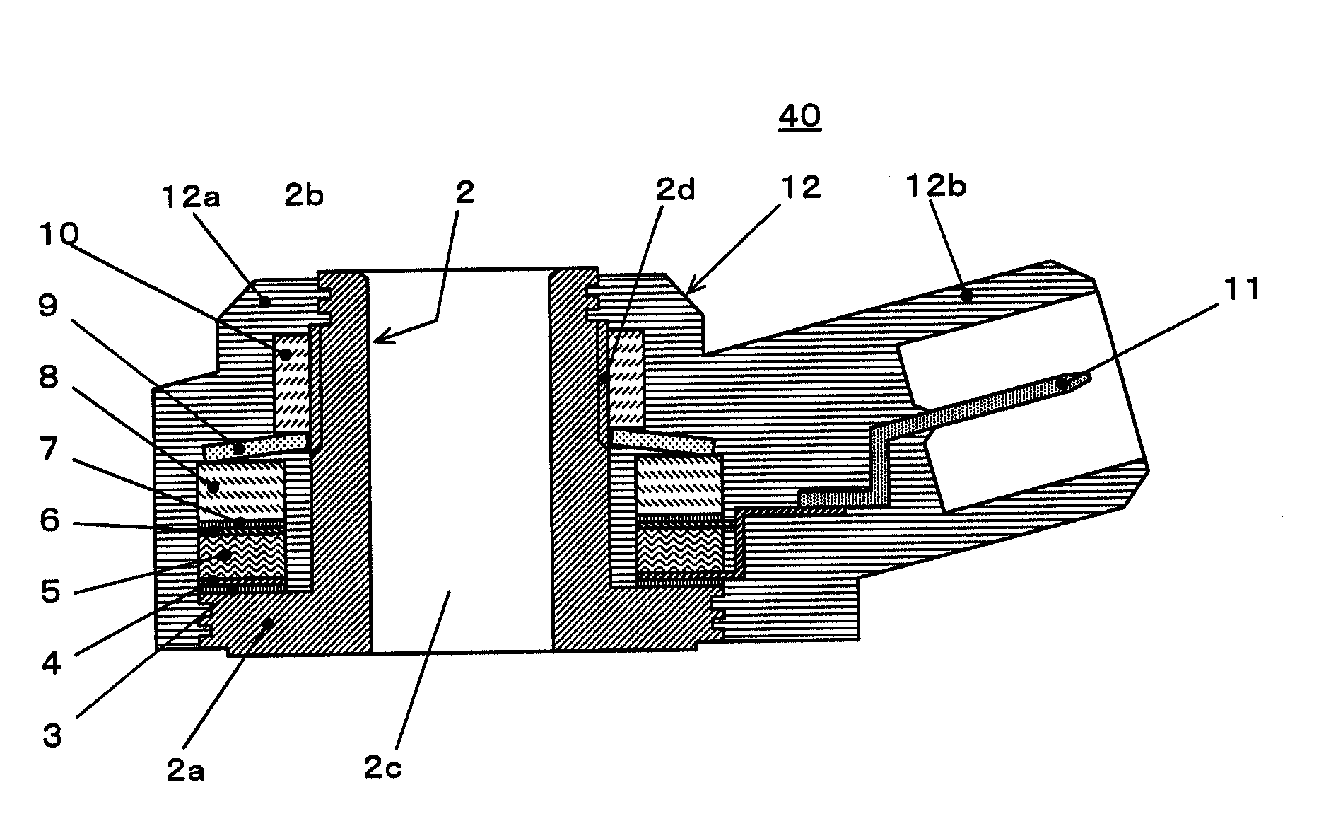
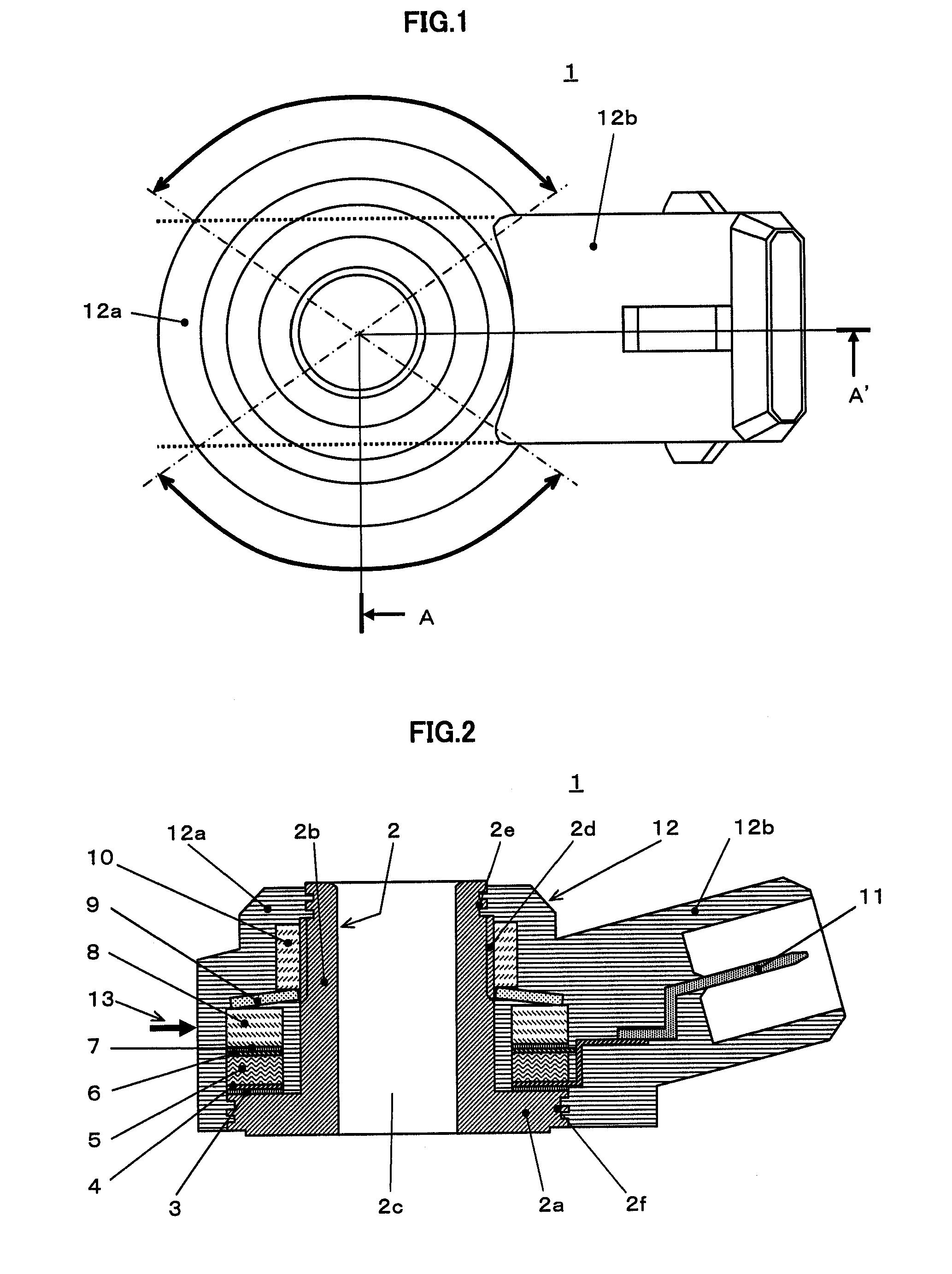
[0029]FIG. 1 is a top external view of the knock sensor according to Embodiment 1 of the present invention, in which a connector section aiming to connect the sensor to external equipment is integrally constructed by resin mold; FIG. 2 is a cross-sectional view of its interior construction along the line A-A′ in FIG. 1.
[0030]In FIG. 1 and FIG. 2, numeral 1 denotes the knock sensor whose constituent parts described later are covered with a resin mold 12 (nylon 66, for example) that is formed by injection-molding from the injection gate 13 (refer to FIG. 2); the resin mold 12 includes a first cylindrical mold section 12a that encloses a metal base 2 described later, annular constituent parts for the knock sensor and a pressing member, and a connector section 12b that is integrally injection-molded at one time with the first cylindrical mold section 12a, prot...
embodiment 2
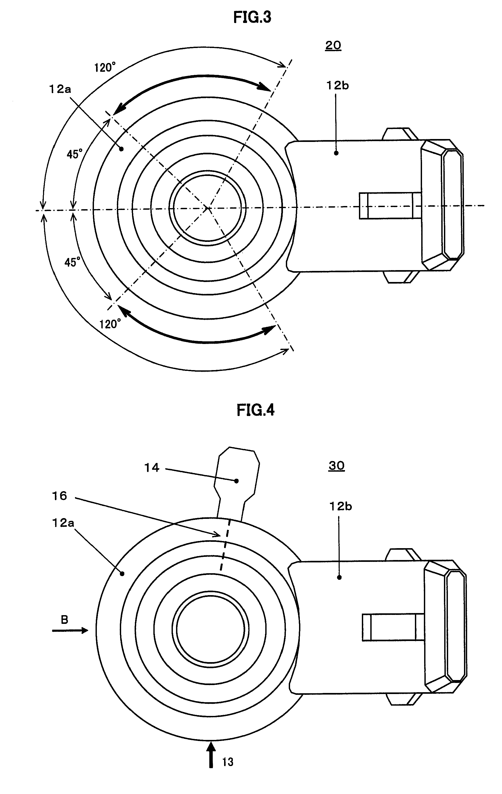
[0038]FIG. 3 is a top external view of a knock sensor 20 according to Embodiment 2 of the present invention. The interior construction of the knock sensor according to Embodiment 2 is the same as that of Embodiment 1 described above; however, in Embodiment 2 the injection gate for resin mold 12 is located in such a way that the gate is on the circumference of the first cylindrical mold section 12a and forms an angle in a range between 45° to 120° with respect to the center line connecting the center of the cylinder section of the base 2 with that of the connector section 12b, namely the protruding section.
[0039]According to Embodiment 2 of the invention, since the injection gate is located taking into consideration productivity in mass production, the same effect as that of Embodiment 1 can be brought about without impairing the strength of the molding die.
embodiment 3
[0040]FIG. 4 is a top external view of a knock sensor 30 according to Embodiment 3 of the present invention, FIG. 5, an external view of the knock sensor viewed from the direction indicated by B in FIG. 4, and FIG. 6, a cross-sectional view along the line C-C′ in FIG. 5.
[0041]While the interior construction of the knock sensor according Embodiment 3 is the same as that of Embodiment 2 described above, the injection gate 13 for the resin mold 12 is located in a position, on the circumference of the first cylindrical mold section 12a, where the gate forms an angle of 90° with respect to the center line connecting the center of the connector section 12b with that of the cylinder section 2b of the base 2. Moreover, although the weld 16 is formed in a position 180° opposing the injection gate, the position in this construction is slightly shifted toward the connector section 12b under the influence of flow balance of mold material for outer covering, due to the connector section 12b. In ...
PUM
 Abstract
Description
Claims
Application Information