
Mould for realizing a temporary prosthesis of hip or shoulder, and method thereof

a temporary prosthesis and mould technology, applied in the direction of prosthesis, femoral head, shoulder joints, etc., can solve the problems of uneven surface, poor inconvenient use of surgeons' antibiotics, etc., to achieve good mechanical and tribological performance, good surface finish, and regular shape

Active Publication Date: 2019-01-17
G21 SRL
View PDF0 Cites 1 Cited by
  • Summary
  • Abstract
  • Description
  • Claims
  • Application Information

AI Technical Summary

Benefits of technology

[0012]In particular, the first insert comprises a cap portion which is conformed and designed to give the desired shape to the head of the temporary prosthesis of hip or shoulder. Said cap portion is dimensioned to be introduced in the head portion of the chamber and is realized as a unique body; such features, combined with the conformation of the first mould portion and the second mould portion, allow to obtain the temporary prosthesis of hip or shoulder with uniform joint surface of the head, i.

Problems solved by technology

However, during the surgery, the surgeon could notice that the ordered temporary prosthesis is not perfectly dimensioned for the patient; in such case, the surgeon has to use said temporary prosthesis anyway, since it is the only one at his disposal.
Moreover, the surgeon has limited freedom concerning the antibiotics to choose to be mixed to the bone cement.
Anyway, the temporary prosthesis of hip or shoulder o

Method used


Image

  • Mould for realizing a temporary prosthesis of hip or shoulder, and method thereof
  • Mould for realizing a temporary prosthesis of hip or shoulder, and method thereof
  • Mould for realizing a temporary prosthesis of hip or shoulder, and method thereof

Examples


Embodiment Construction

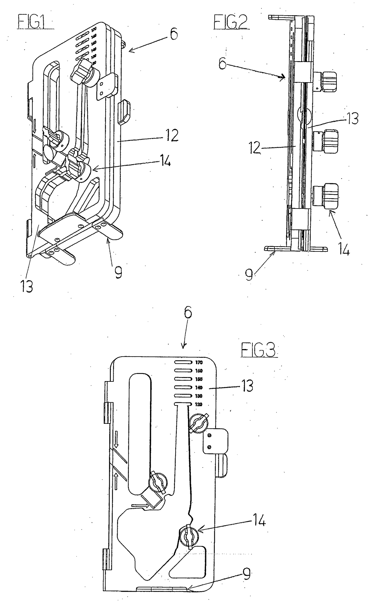
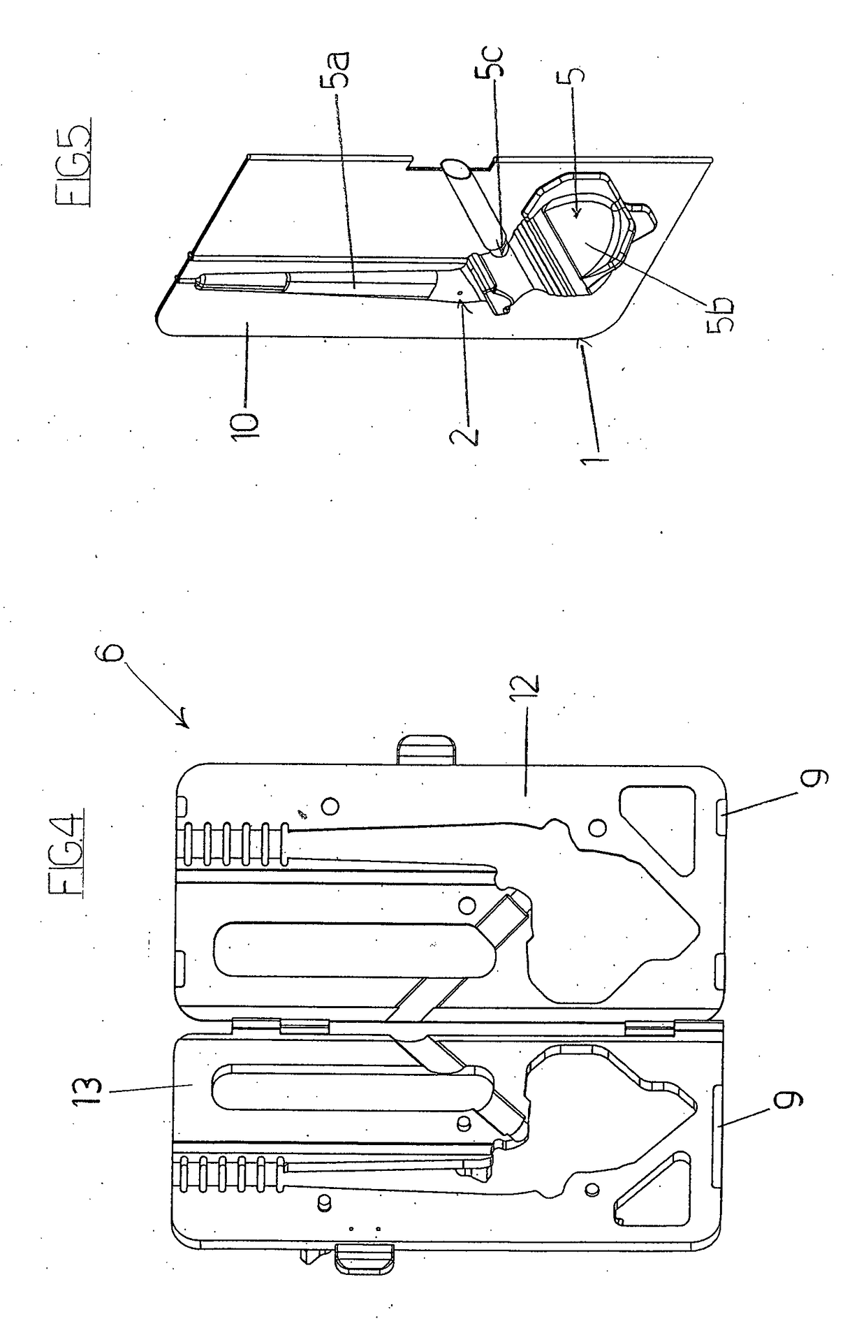
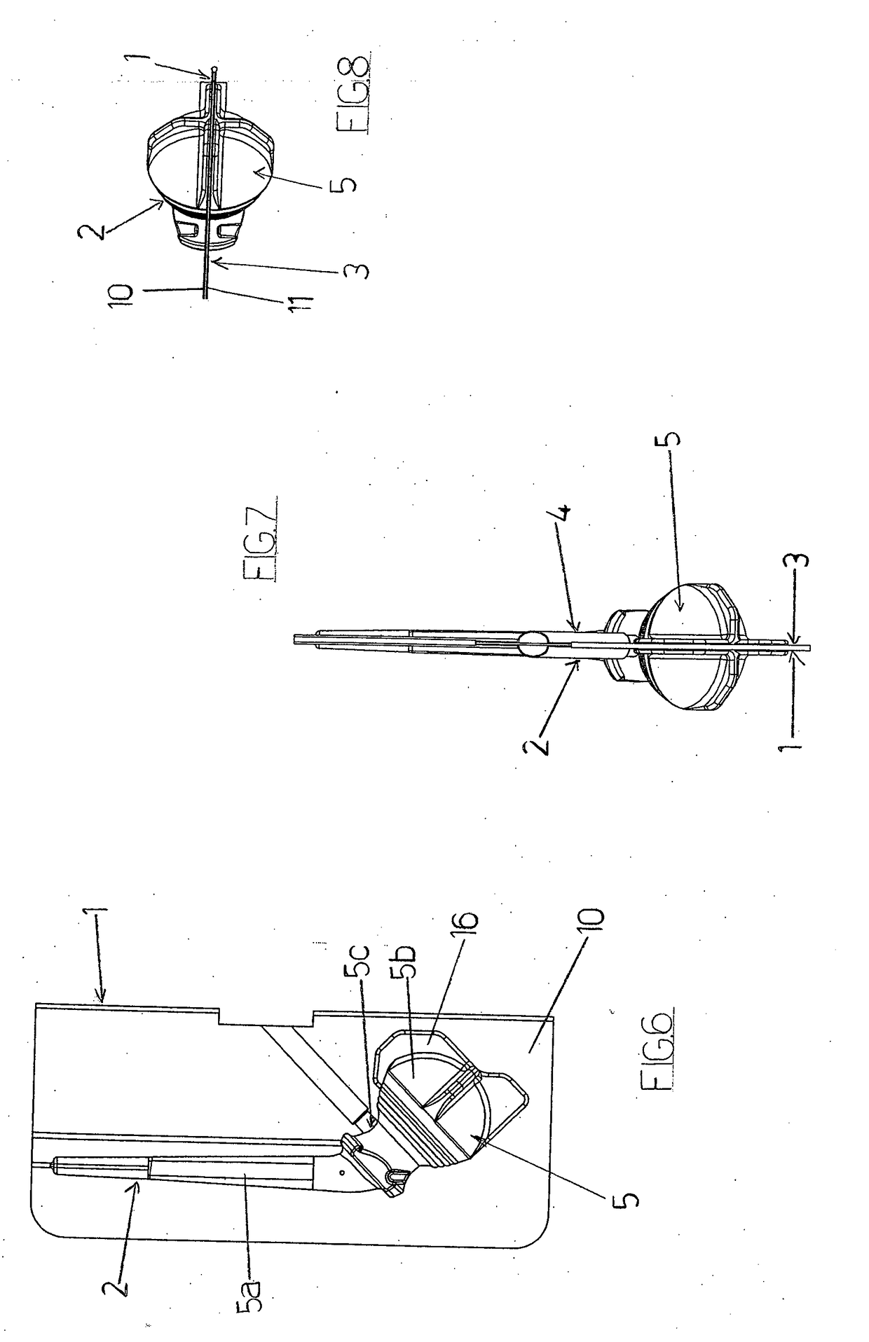
[0031]With reference to the appended drawings, FIGS. 1-13 show an embodiment of elements of a mould, object of the present invention, for realizing a temporary prosthesis of hip. Similarly, FIGS. 14-23 show an embodiment of elements of a mould, object of the present invention, for realizing a temporary prosthesis of shoulder.

[0032]A temporary prosthesis of hip or shoulder comprises a shaft and a head fixed to the shaft.

[0033]The proposed mould comprises a first mould portion (1) comprising a first half-shell (2), and a second mould portion (3) comprising a second half-shell (4). The first mould portion (1) and the second mould portion (3) can be coupled with respect to each other so that, when coupled, the first half-shell (2) and the second half-shell (4) are counter-faced and define a chamber (5) which conforms a shaft portion (5a), a head portion (5b) and an opening (5c) for injection in the same chamber (5) of a suitable fluid (preferably viscous, as for example polymethylmethac...


PUM


Abstract

Mould and method for realizing a temporary prosthesis of hip or shoulder, which comprises a shaft and a head. The mould comprises: a first mould portion (1) comprising a first half-shell (2); a second mould portion (3) comprising a second half-shell (4); the first mould portion (1) and the second mould portion (3) being able to be coupled with respect to each other so that the first and second half-shell (2, 4) are counter-faced and define a chamber (5) which conforms a shaft portion (5a), a head portion (5b) and an opening (5c) for injection of a fluid (preferably viscous) material; fixing means (6) for fixing the first and the second portion (1, 3); a first insert (7) comprising a cap portion (8) which is realized as a unique body, is dimensioned to be inserted in the head portion (5b) and is conformed to give shape to the head of the prosthesis. The first mould portion (1), the second mould portion (3) and the first insert (7) are mutually conformed to obtain a temporary prosthesis, when the first mould portion (1) and the second mould portion (3) are coupled together, the first insert (7) is inserted in the head portion (5b) and the fluid (preferably viscous) material is injected in the opening (5c).

Description

FIELD OF THE INVENTION[0001]The present invention relates to the technical field of the temporary prosthesis of hip or shoulder. In particular, the present invention relates to a mould for realizing a temporary prosthesis of hip or shoulder and a method thereof. Yet, the invention relates to a mould usable during the implantation surgical procedure of a temporary prosthesis of hip or shoulder.STATE OF THE ART[0002]A temporary prosthesis (also called spacer) is a medical device used in the infections treatment of joint prostheses. In particular, in case of a patient with an infected definitive prosthesis, the surgeon proceeds to the removal of the infected definitive prosthesis, to tissues surgical cleaning and to the positioning of a temporary prosthesis. Said temporary prosthesis, usually realized in bone cement and able to release antibiotics, is held implanted for some months to cure the infection. In the following, the surgeon proceeds to the removal of the temporary prosthesis,...

Claims


Application Information

Patent Timeline
IPC IPC(8): A61F2/30B29C45/14
CPCA61F2/30B29C45/14065A61F2002/30672B29L2031/7532B29K2033/12B29K2823/06B29C2045/14131A61F2002/30975A61F2/3094A61F2/36A61F2/4059A61F2002/30616A61F2002/3611A61F2002/4018A61F2310/00353
Inventor MANTOVANIBAETTA, DANIELE
Owner G21 SRL
Learn More