Apparatus and method for improving work surface during forming and shaping of materials

a technology of material forming and material surface, applied in the direction of turning machines, vehicle heating/cooling devices, turning machines, etc., can solve the problems of not solving the problems or satisfying the needs, and neither the prior art references nor the publications discussed herein solve the problems or the needs, and achieve the effect of improving the surface finish and/or surface integrity of the workpi

Active Publication Date: 2005-09-29
AIR PROD & CHEM INC
View PDF15 Cites 48 Cited by
  • Summary
  • Abstract
  • Description
  • Claims
  • Application Information

AI Technical Summary

Benefits of technology

[0017] Applicants' invention is a method and an apparatus for improving the surface finish and / or surface integrity of a workpiece formed or shaped with a tool. Another aspect of the invention is a method and an apparatus for forming or shaping a workpiece. Yet another aspect of the invention is a method and an apparatus for manufacturing a finished part or a finished product from a workpiece. Other aspects of the invention are a workpiece formed or shaped by the method and apparatus for forming or shaping a workpiece, and a finished part or a finished product manufactured by the method and apparatus for manufacturing. The invention also includes a nozzle for jetting an expanding jet of a cryogen to a surface of a workpiece.

Problems solved by technology

The patent does not, however, teach how to improve productivity, increase cutting tool life, or reduce the roughness of a work surface.
However, none of these publications nor the other prior art references discussed herein solve the problems or satisfy the needs discussed herein.
The methods taught by these two patents improve tool productivity, but the first method cannot effectively control work surface finish and integrity, and the second method requires extensive machine tool modifications that would be unacceptably expensive in most industrial applications.
By cooling the chip, rather than the cutting tool or the polymer workpiece, the method does not improve tool productivity or workpiece surface finish and integrity.
The key methods for correcting residual surface stress distribution (i.e., increasing its compressive component) include shot peening and laser peening, both of which are known to deteriorate or damage work surface finish and increase work roughness if applied to their fullest extent.
These four patent publications show two critical and still unsolved issues facing the industry: (a) a frequent need for an additional, expensive manufacturing step fixing residual surface stresses and following the forming or shaping steps, and (b) the present trade-offs between the surface finish and the compressive stress imparted during the stress fixing operations.
Clearly, there is an unsatisfied need for an improved forming, shaping and machining technique which would enhance surface finish and compressive stresses at the same time without requiring additional manufacturing steps.

Method used


Image

  • Apparatus and method for improving work surface during forming and shaping of materials
  • Apparatus and method for improving work surface during forming and shaping of materials
  • Apparatus and method for improving work surface during forming and shaping of materials

Examples


example 1

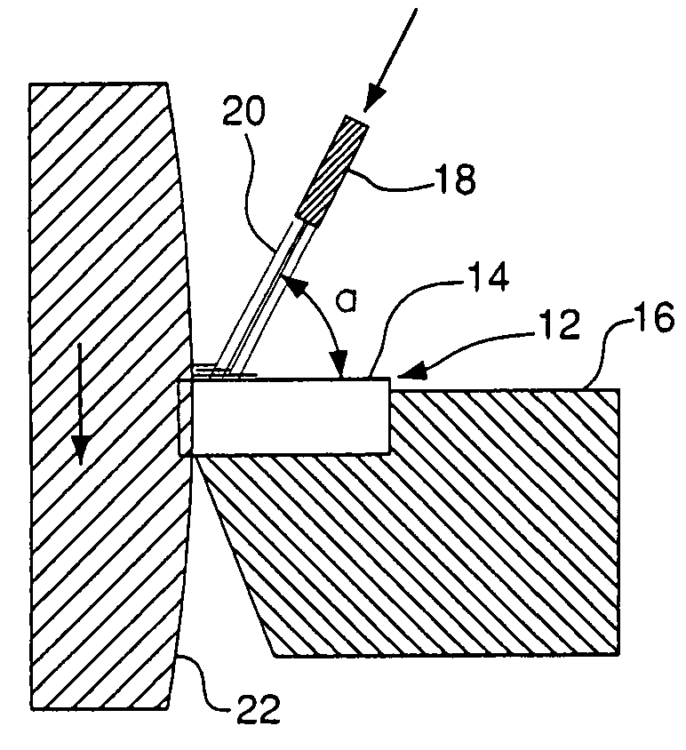
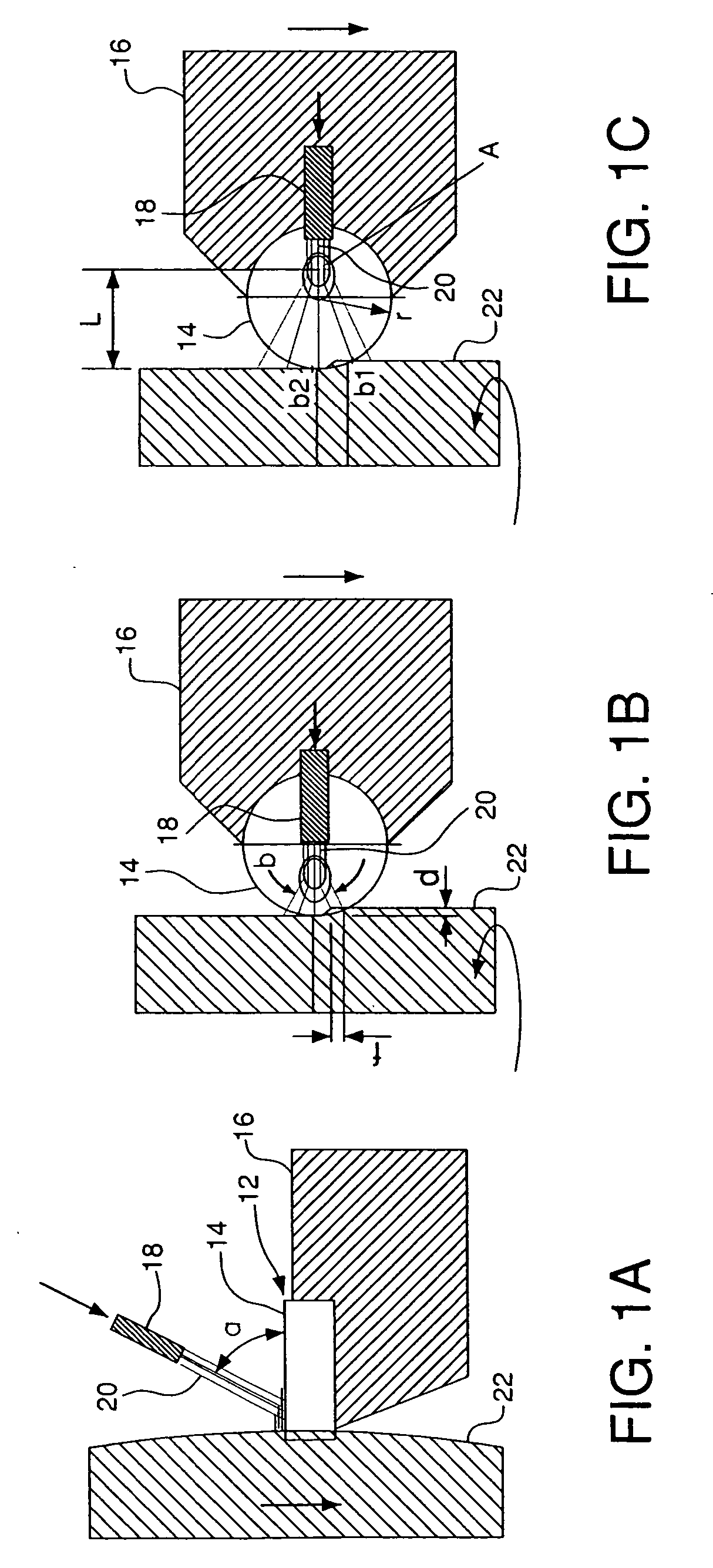
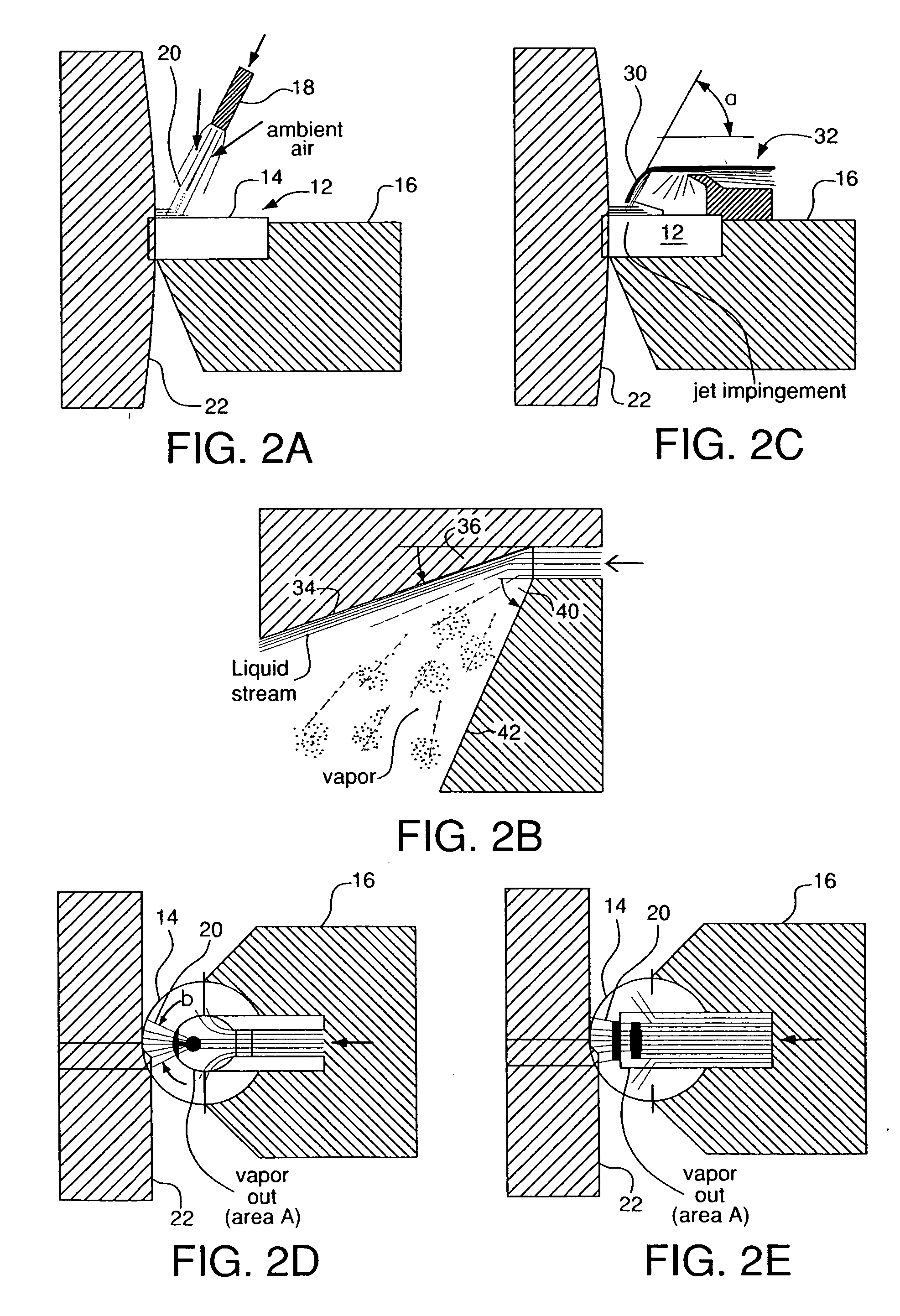
[0109] The effect of the cryogenic jet impingement angle (α) on cooling of a cutting insert was evaluated for various flowrates and supply pressures. Liquid nitrogen (LIN) coolant was jetted using two simple, tubular nozzles such as that shown in FIG. 2A. The internal termination of the nozzles was shaped to form a converging-diverging (CD), Laval-type fluidic passage which can focus expanding cryogenic jets more precisely than straight-wall or converging-only fluid passages. The narrowest section of the throat of the first CD nozzle was 0.019 inches in diameter, and the second CD nozzle was 0.025 inches in diameter. At the supply pressure of 120 psig, the smaller nozzle jetted 1.1 lbs / minute of LIN, and the larger nozzle jetted 1.8 lbs / minute of LIN. An additional test with the larger nozzle at the reduced supply pressure of 60 psig showed that the expanding jet was more confined or less bushy, and its flowrate was 1.2 lbs / minute of LIN.

[0110] LIN jets produced by each nozzle were...

example 2

[0112] Iron, graphite, copper, and nickel powders were premixed to obtain the FN-0208 (MPIF class) composition (0.8-0.9% C, 0.8% Ni, 2.0% Cu, bal.Fe, all on weight basis), pressed into powder metallurgy (P / M) disks, and sintered to achieve two different density levels: 6.67 g / cm3 (6.67 Mg / m3), ‘low-density’ material, 14.5% porosity fraction, and 7.20 g / cm3 (7.20 Mg / m3), ‘high-density’ material, 7.7% porosity fraction. Half of the disks from each density group were subsequently case hardened by heat-treating using the conventional procedures for achieving a high-level apparent hardness—at least 30 HRC in the case of the low density material, and at least 40 HRC in the case of the high density material.

[0113] Surface machining of so prepared P / M disks was carried out on a 20 kW CNC lathe, constant speed operation, using the following parameters: (1) cutting speed—1,000 ft / min. (305 m / min. or 5.08 m / s); (2) feedrate—0.007 inch / rev. (0.178 mm / rev.); and (3) depth of cut —0.008 inches ...

example 3

[0115] The as-sintered, soft P / M disks from Example 2 were surface machined using liquid nitrogen (LIN) cryogenic jet cooling and a tool-clamping nozzle with an internal expansion chamber as shown in FIGS. 2C and 2D. At the LIN mass-flowrate of 1.8 lbs / minute, and the supply pressure of 100 psig (6.89 bar), the nozzle produced a jet impringing at the rake surface under the impingement angle (α) equal 45° and spreading to the sides under the spread angle (β) equal 90°. A cost-effective, commercially available, Al2O3—TiC based, TiN-coated (PVD), fine-grained black ceramic cutting insert was used which had four (4) cutting edges and geometry specified as follows: CNGA-433, 0.008-inch land (0.200 mm wide chamfer), −25° chamfer angle. Apart from the different insert and cooling method, all other conditions were the same as in Example 2.

[0116] Table 2 compares the as-machined surface roughness of flood and LIN machined disks and the life of cutting edge before an average tool flank wear ...


PUM

PropertyMeasurementUnit
impingement angleaaaaaaaaaa

Abstract

A method and apparatus for improving the surface finish and/or surface integrity of a workpiece formed or shaped with a tool increase the surface hardness of the workpiece during forming or shaping of the workpiece. A method and apparatus for forming or shaping a workpiece also increase the surface hardness of the workpiece during forming or shaping of the workpiece with a tool, as do a method and apparatus for manufacturing a finished part or product from a workpiece. In some embodiments, an expanding jet of cryogen may be jetted to a surface of a workpiece and a tool from a nozzle, wherein the cryogen is at least partially separated into a condensed phase portion and a vapor portion within a downstream portion of the nozzle.

Description

BACKGROUND OF THE INVENTION [0001] The present invention relates to the field of forming and shaping of materials by various processes, including but not limited to cutting (e.g., shaping parts by removing excess material in the form of chips) and other types of machining, and more particularly improving surface finish and surface integrity of metals and other engineering materials (e.g., polymers and various types of composite materials) formed and shaped through such processes by utilizing cryogenic cooling and other types of treatments, including but not limited to heat treatment, chemical treatment, and mechanical treatment. [0002] As used herein, the term “cutting” includes but is not limited to the following operations: turning, boring, parting, grooving, facing, planning, milling, drilling, and other operations which generate continuous chips or fragmented or segmented chips. The term cutting does not include: grinding, electro-discharge machining, or high-pressurejet erosion...

Claims


Application Information

Patent Timeline
Patent Type & Authority Applications(United States)
IPC IPC(8): B23B27/10B23P25/00B23Q11/10C21D1/613C21D7/04C21D9/00
CPCB23P25/003B23Q11/1053Y10T82/10C21D7/04C21D2261/00C21D1/613B23Q11/1061B60H1/0065H01H19/08H01H19/14H01H2231/026
Inventor ZURECKI, ZBIGNIEWGHOSH, RANAJITFREY, JOHN HERBERTGRIMM, LANCE MICHAEL
Owner AIR PROD & CHEM INC
Why Eureka
Try Eureka