Mould for Preparing Large Structures, Methods of Preparing Mould and Use of Mould

a technology for moulds and structures, applied in the field of moulds for preparing large structures, can solve the problems of unsuitable pressing film, unsuitable large-scale mouldings, expensive and difficult to handle, etc., and achieve the effect of reducing the number and size of sink marks and increasing the tolerance to air leakag

Inactive Publication Date: 2008-10-02
VESTAS WIND SYST AS
View PDF11 Cites 49 Cited by
  • Summary
  • Abstract
  • Description
  • Claims
  • Application Information

AI Technical Summary

Benefits of technology

[0011]The mould according to the invention is advantageous over prior art moulds in that it provides the ability to manufacture very large moulded items, such as a wind turbine blade, and one or more of: more robust air-removal from the mould via the air-permeable surface member and the air-drainage system; increased tolerance to air leakage through the support structure; reduced number and size of sink marks in the moulded item; ability to provide in-mould coating; and improved surface finish of the moulded item.

Problems solved by technology

Pressing the film down is not suitable for large size mouldings, such as a wind turbine blade or shell, as the matching mould and press would have to be very large and therefore expensive and difficult to handle.
Unfortunately, air tends to become trapped between the film and the mould during evacuation resulting in undesired shape of the moulded item.
However, for hot cure none of these alternatives are acceptable as the film will soften during the cure cycle of the moulded item and therefore an imprint of the texture of the mould surface will be produced in the film, resulting in an unacceptable surface finish of the coating on the moulded item.
Despite measures to ensure an airtight mould, such moulds will often have some porosity or micro cracks leading to air leaking through the mould wall.
An air leak under the film will in most cases make a drop in vacuum under the film resulting in the risk that the film does not stay firmly attached to the mould during processing of the item to be moulded.
Furthermore, air leaks will result in sink marks on the moulded item.
Such a mould is rather complicated to produce and is not suitable for moulding of large items.

Method used


Image

  • Mould for Preparing Large Structures, Methods of Preparing Mould and Use of Mould
  • Mould for Preparing Large Structures, Methods of Preparing Mould and Use of Mould
  • Mould for Preparing Large Structures, Methods of Preparing Mould and Use of Mould

Examples


Embodiment Construction

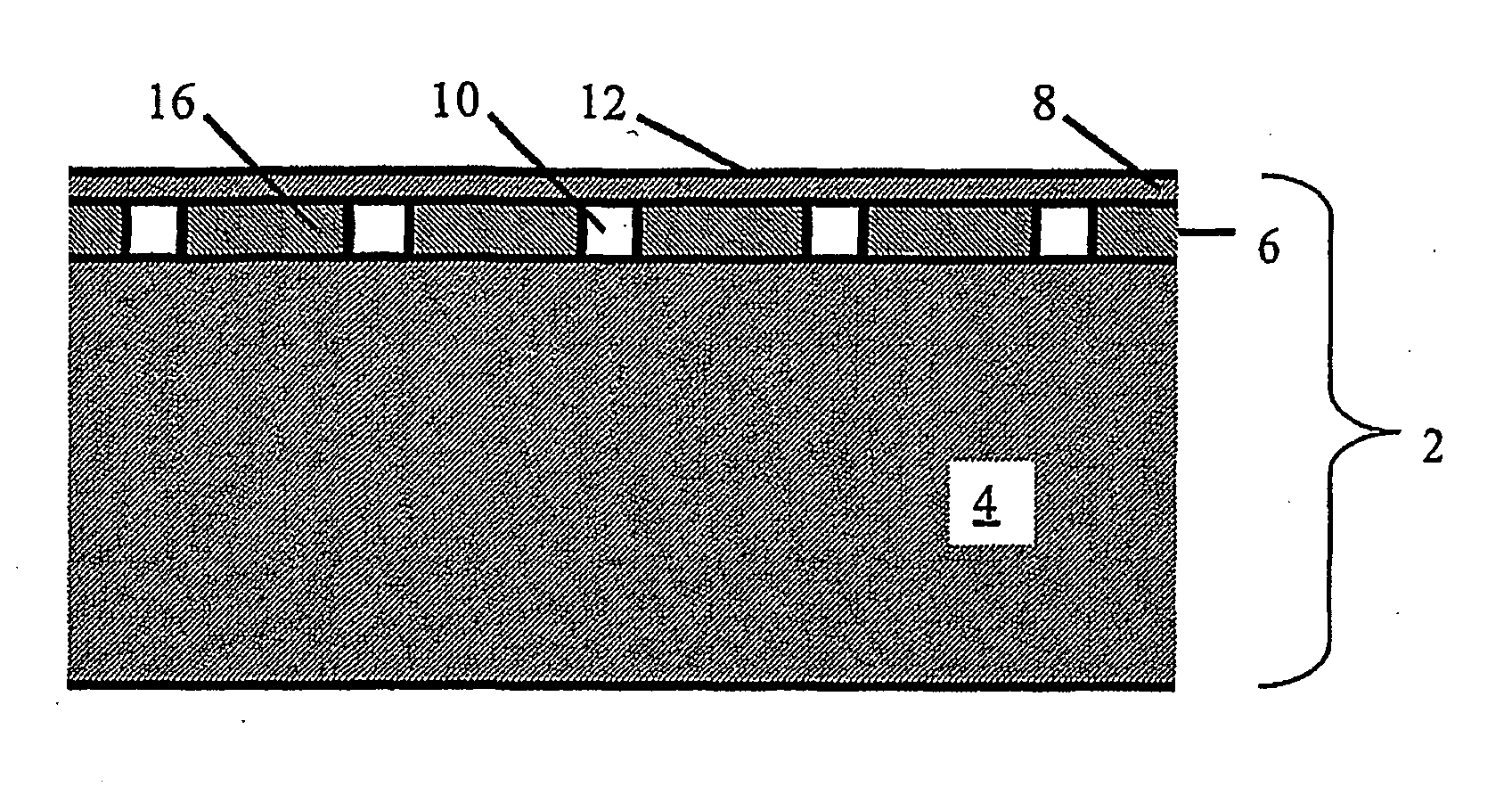
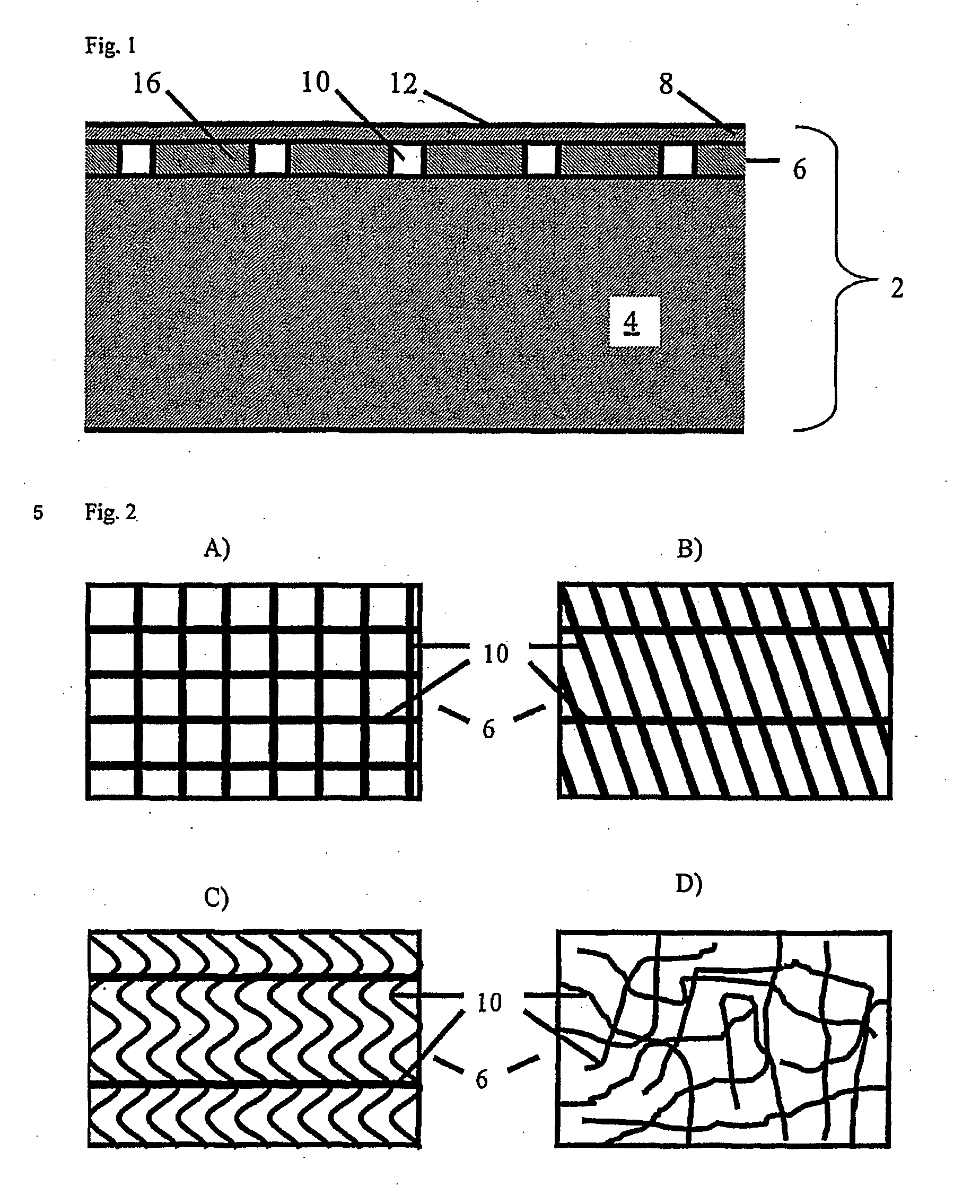
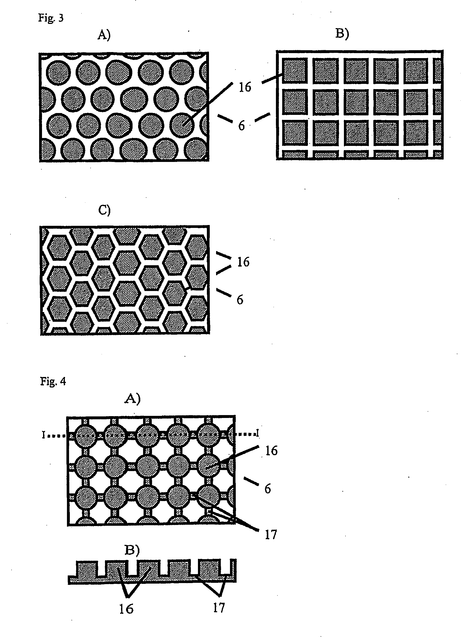
[0024]The mould according to the invention is typically rather large, such as in the order of 10 to 70 meters and to be able to identify smaller features, only limited sections are shown in the figures. This is also the case in FIG. 1 where a cross section of a mould 2 is shown.

[0025]The mould in FIG. 1 has a support structure 4 to which an air-drainage system 6 is connected. Finally, an air-permeable surface member 8 is positioned on the air-drainage system 6 to form the active mould surface 12.

Support Structure

[0026]The support structure 4 typically provides a major part of the load-bearing ability of the mould even though in some embodiments the air-permeable surface member and / or the air-drainage system may account for a significant part of the load bearing. Furthermore, the support structure usually provides the rough shape of the active mould surface even though the air-permeable surface member and / or the air-drainage system may provide smaller adjustments in the shape.

[0027]T...


PUM

PropertyMeasurementUnit
distanceaaaaaaaaaa
distanceaaaaaaaaaa
distanceaaaaaaaaaa

Abstract

A mould (2) for preparing of large structures, such as wind turbine blades, is provided. Furthermore, methods of manufacturing and use of such a mould (2) are provided. The mould (2) comprises a support structure (4), an air-drainage structure (6) and an air-permeable surface member (8). Ile mould is particularly suitable for preparing of moulded items with an in-mould coating.

Description

TECHNICAL FIELD OF THE INVENTION[0001]The present invention relates to a mould for preparing large structures, such as wind turbine blades. Particularly, the present invention relates to a mould comprising an air-permeable surface member and an air-drainage structure, a method of preparing such an air-permeable surface and a method of use of such a mould. Such a mould is particularly suitable for the manufacturing of a wind turbine blade with an in-mould coat.BACKGROUND OF THE INVENTION[0002]Many composite items are prepared with a coating. Traditionally, the item has been painted after moulding. Today, it is known to process the item with an in-mould coating, such as a thermoplastic film, to form a surface film. During processing, the film has be to held to the surface of the mould either by sucking the film onto the tool surface by vacuum or by pressing the film down onto the tool surface by air or mechanical pressure. Pressing the film down is not suitable for large size moulding...

Claims


Application Information

Patent Timeline
Patent Type & Authority Applications(United States)
IPC IPC(8): B29C70/02B22F3/11B22F5/00B29C33/10B29C33/38B29C33/56B29C37/00B29C70/08B29D99/00F03D1/06
CPCB22F5/007B22F2999/00B29C33/3814B29C37/0032B29C37/0067B29C70/086B29C70/443B29C70/543B29L2031/082F03D1/065Y02E10/721B22F7/002B29C33/10B29C33/68Y02E10/72Y02P70/50
Inventor BECH, ANTON
Owner VESTAS WIND SYST AS
Why Eureka
Try Eureka