Injection molding of metallic glass by rapid capacitor discharge

a capacitor discharge and injection molding technology, applied in the direction of foundry moulds, metal-working apparatus, heat treatment process control, etc., can solve the problems of limited use of early amorphous alloys as bulk objects and articles, limited size of early amorphous alloys, and inconvenient casting processes for such high cooling rates. , to achieve the effect of avoiding failure by necking

Active Publication Date: 2013-01-31
CALIFORNIA INST OF TECH
View PDF7 Cites 47 Cited by
  • Summary
  • Abstract
  • Description
  • Claims
  • Application Information

AI Technical Summary

Benefits of technology

[0030]In still yet another embodiment, the tensile deformational force is controlled so that the flow of the material is Newtonian and failure by necking is avoided.
[0031]In still yet another embodiment, the tensile deformational rate is controlled so that the flow of the material is Newtonian and failure by necking is avoided.

Problems solved by technology

As such, conventional casting processes were not suitable for such high cooling rates, and special casting processes such as melt spinning and planar flow casting were developed.
Due to the crystallization kinetics of those early alloys being substantially fast, extremely short time (on the order of 10−3 seconds or less) for heat extraction from the molten alloy were required to bypass crystallization, and thus early amorphous alloys were also limited in size in at least one dimension.
Because the critical cooling rate requirements for these amorphous alloys severely limited the size of parts made from amorphous alloys, the use of early amorphous alloys as bulk objects and articles was limited.
However, even though bulk-solidifying amorphous alloys provide some remedy to the fundamental deficiencies of solidification casting, and particularly to the die-casting and permanent mold casting processes, as discussed above, there are still issues which need to be addressed.
For example, presently available BMGs with large critical casting dimensions capable of making large bulk amorphous objects are limited to a few groups of alloy compositions based on a very narrow selection of metals, including Zr-based alloys with additions of Ti, Ni, Cu, Al and Be and Pd-based alloys with additions of Ni, Cu, and P, which are not necessarily optimized from either an engineering or cost perspective.
In addition, the current processing technology requires a great deal of expensive machinery to ensure appropriate processing conditions are created.
These modified die-casting machines can cost several hundreds of thousands of dollars per machine.
Because the “critical casting dimension” is correlated to the critical cooling rate, these conventional processes are not suitable for forming larger bulk objects and articles of a broader range of bulk-solidifying amorphous alloys.
Because the metal is fed into the die under high pressure and at high velocities, such as in high-pressure die-casting operation, the flow of the molten metal becomes prone to Rayleigh-Taylor instability.
This flow instability is characterized by a high Weber number, and is associated with the break-up of the flow front causing the formation of protruded seams and cells, which appear as cosmetic and structural micro-defects in cast parts.
Also, there is a tendency to form a shrinkage cavity or porosity along the centerline of the die-casting mold when unvitrified liquid is trapped inside a solid shell of vitrified metal.
None of these prior art methods teach how to uniformly heat the entire BMG specimen volume in order to be able to perform global forming.
Another drawback of the limited stability of BMGs against crystallization above the glass transition is the inability to measure thermodynamic and transport properties, such as heat capacity and viscosity, over the entire range of temperatures of the metastable supercooled liquid.

Method used


Image

  • Injection molding of metallic glass by rapid capacitor discharge
  • Injection molding of metallic glass by rapid capacitor discharge
  • Injection molding of metallic glass by rapid capacitor discharge

Examples


example 1

Study of Ohmic Heating

[0132]To demonstrate the basic principle that for BMGs capacitive discharge with Ohmic heat dissipation in a cylindrical sample will give uniform and rapid sample heating a simple laboratory spot welding machine was used as a demonstration shaping tool. The machine, a Unitek 1048 B spot welder, will store up to 100 Joules of energy in a capacitor of ˜10 μF. The stored energy can be accurately controlled. The RC time constant is of order 100 μs. To confine a sample cylinder, two paddle shaped electrodes were provided with flat parallel surfaces. The spot welding machine has a spring loaded upper electrode which permits application of an axial load of up to ˜80 Newtons of force to the upper electrode. This, in turn permits a constant compressive stress ranging to ˜20 MPa to be applied to the sample cylinder.

[0133]Small right circular cylinders of several BMG materials were fabricated with diameters of 1-2 mm and heights of 2-3 mm. The sample mass ranged from ˜40 ...

example 2

Injection Molding Apparatus

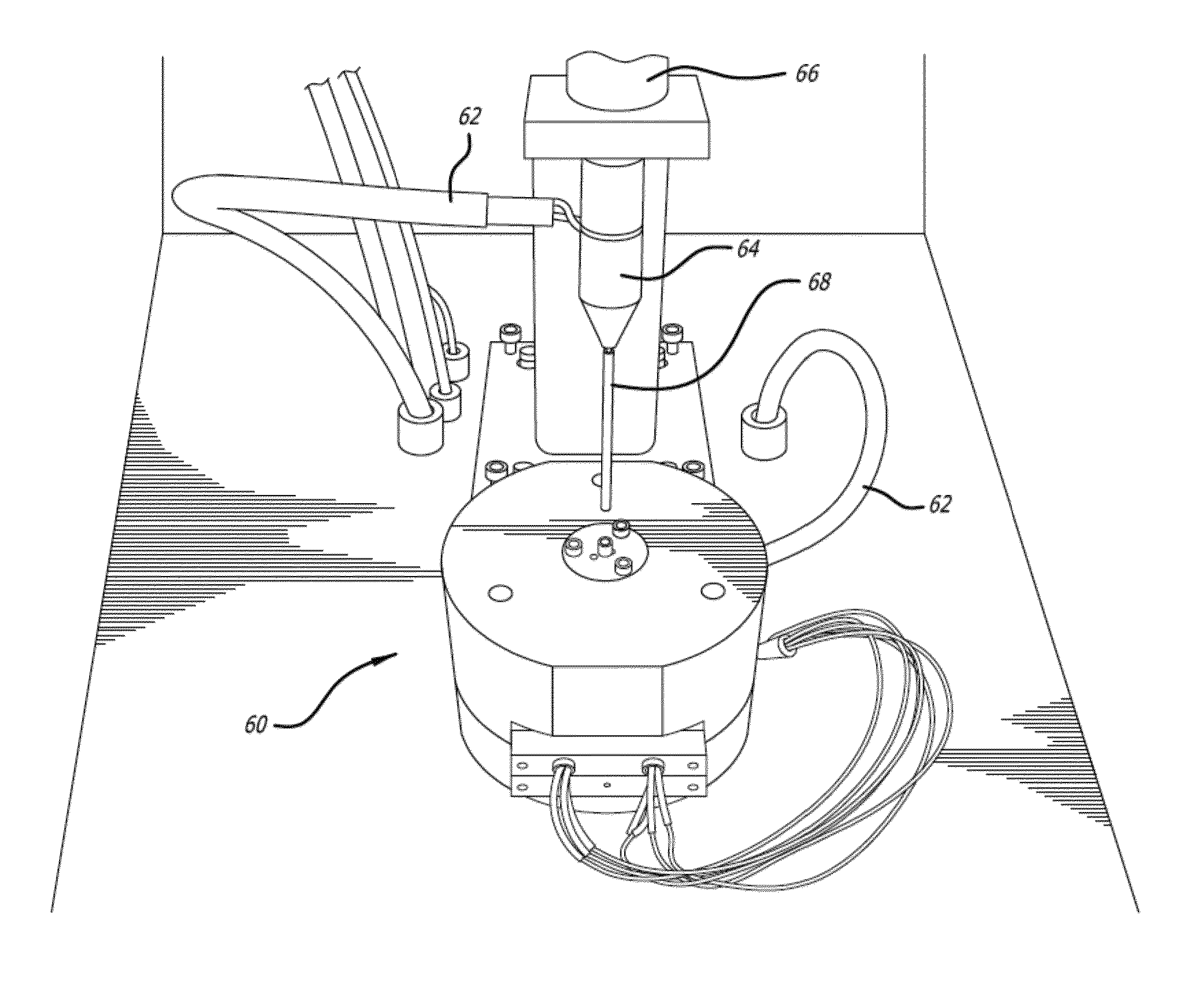
[0137]In another example, a working prototype RCDF injection molding apparatus was constructed. Schematics of the device are provided in FIGS. 11a to 11e. Experiments conducted with the shaping apparatus prove that it can be used to injection mold charges of several grams into net-shape articles in less than one second. The system as shown is capable of storing an electrical energy of ˜6 KJoules and applying a controlled process pressure of up to ˜100 MPa to be used to produce small net shape BMG parts.

[0138]The entire machine is comprised of several independent systems, including an electrical energy charge generation system, a controlled process pressure system, and a mold assembly. The electrical energy charge generation system comprises a capacitor bank, voltage control panel and voltage controller all interconnected to a mold assembly (60) via a set of electrical leads (62) and electrodes (64) such that an electrical discharge of may be applied to the...

example 3

Apparatus for Injection Molding of Metallic Glasses

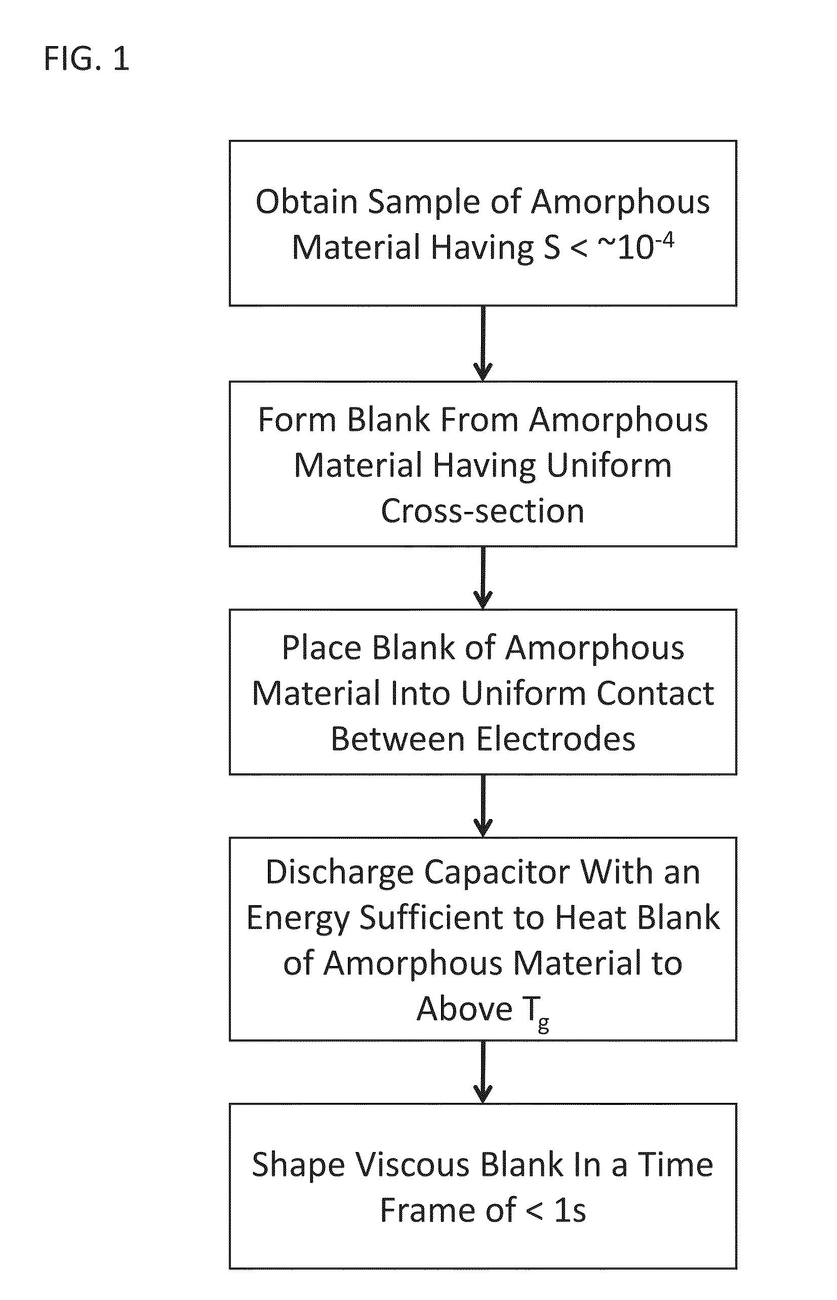
[0143]As described briefly above, the RCDF method of the current invention can be used to heat and shape a wide-variety of metallic glasses utilizing dissipation of electrical current to uniformly heat a metallic glass charge at time scales far shorter than typical times associated with crystallization, and that this technique may be used for a number of processes, including injection molding. Injection molding of polymeric materials involves uniform heating of polymeric feedstock, usually in the form of pellets, to temperatures above the softening (glass-transition) point reaching viscosities in the range of 100 to 10000 Pa-s, and subsequently with the application of a force, delivered for example with a hydraulically driven plunger, force the melt into a die cavity having a desired shape where it is formed and simultaneously cooled to below the softening point. Like polymers, metallic glasses also soften above their glass-transiti...


PUM

PropertyMeasurementUnit
temperatureaaaaaaaaaa
electrical energyaaaaaaaaaa
viscosityaaaaaaaaaa

Abstract

An apparatus and method of uniformly heating, rheologically softening, and thermoplastically forming magnetic metallic glasses rapidly into a net shape using a rapid capacitor discharge forming (RCDF) tool are provided. The RCDF method utilizes the discharge of electrical energy stored in a capacitor to uniformly and rapidly heat a sample or charge of metallic glass alloy to a predetermined “process temperature” between the glass transition temperature of the amorphous material and the equilibrium melting point of the alloy in a time scale of several milliseconds or less. Once the sample is uniformly heated such that the entire sample block has a sufficiently low process viscosity it may be shaped into high quality amorphous bulk articles via any number of techniques including, for example, injection molding, dynamic forging, stamp forging, sheet forming, and blow molding in a time frame of less than 1 second.

Description

CROSS-REFERENCE TO RELATED APPLICATIONS[0001]This application is a continuation-in-part of U.S. application Ser. No. 12 / 409,253, filed Mar. 23, 2009, and claims priority to U.S. Provisional Application No. 61 / 070,284, filed Mar. 21, 2008, this application also claims priority to U.S. Provisional Application No. 61 / 443,596, filed Feb. 16, 2011, the disclosures of each of which are incorporated herein by reference.FIELD OF THE INVENTION[0002]This invention relates generally to a novel method of forming metallic glass; and more particularly to a process for forming ferromagnetic metallic glasses using rapid capacitor discharge heating.BACKGROUND OF THE INVENTION[0003]Amorphous materials are a new class of engineering material, which have a unique combination of high strength, elasticity, corrosion resistance and processability from the molten state. Amorphous materials differ from conventional crystalline alloys in that their atomic structure lacks the typical long-range ordered patter...

Claims


Application Information

Patent Timeline
Patent Type & Authority Applications(United States)
IPC IPC(8): B22D23/00B22C9/08B22D17/00
CPCC21D1/40C21D7/13C21D11/00C21D2201/03C22C45/00C22C45/10C22F1/00C22C1/002C22C33/003C22C45/02C22C45/003C22C1/11B22D17/20B22D17/00B22D17/02B22D17/32
Inventor DEMETRIOU, MARIOS D.SCHRAMM, JOSEPH P.KALTENBOECK, GEORGJOHNSON, WILLIAM L.
Owner CALIFORNIA INST OF TECH
Why Eureka
Try Eureka