
Dismantlable anechoic chamber

Active Publication Date: 2019-01-17
JUNGBAUER GUILLERMO RAMON ALEJANDRO
View PDF0 Cites 0 Cited by
  • Summary
  • Abstract
  • Description
  • Claims
  • Application Information

AI Technical Summary

Benefits of technology

The present invention is a solution for creating an anechoic chamber that is easy to assemble and dismantle while still effectively attenuating sound. The invention uses a combination of features, including sound-attenuating foam material and air-filled cells, to replace the elastomer material and provide physical damping. Different layer thicknesses ensure that the panels and battens behave differently to produce the damping behavior of the batten. Pre-pressing is used to create a tight fit by causing slight permanent deformations of different sizes in the panels and battens. A damping layer is also used in the interface between vertical battens to prevent sounds being generated by vibration. The present invention provides a simple and advantageous solution for creating dismantlable anechoic chambers.

Problems solved by technology

The ability of said chambers to be moved to different places causes construction problems because, in order to be able to install them in homes, it is necessary to “break” the chamber into prefabricated pieces that can fit through the door or windows of a house.
However, reducing the size of the prefabricated pieces is a problem because the gaps therebetween have paths for the sound which can diminish the soundproofing properties of the chamber, and connecting the panels anechoically in situ is also difficult.
FR 2425009 does not disclose dimensional interference between panels and battens, nor does it require such for its proper functioning.
However, one problem linked with this solution is that the elastomer materials can deform over time, and that, once deformed, they also take a long time to return to a similar state to the initial one.
As a result, after dismantling the chamber and reassembling it, the chamber loses some acoustic properties because of the semi-permanent deformation of the elastomer material.
This is exacerbated if the chamber is dismantled in a careless manner, causing additional stresses in the elastomer material.

Method used


Image

  • Dismantlable anechoic chamber
  • Dismantlable anechoic chamber
  • Dismantlable anechoic chamber

Examples


Embodiment Construction

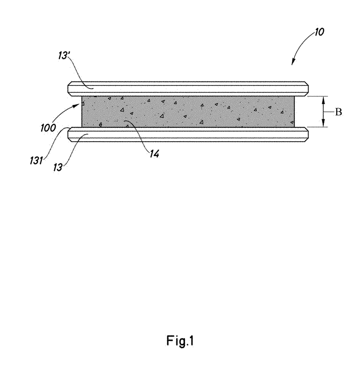
[0024]FIG. 1 shows a planar panel -10- consisting of two sheets -13-, -13′- that have an outer surface coating and enclose a sound-insulating material -14- in a sandwich-like manner. The sound-insulating material -14- is a foam material. The surface area of the sheets -13-, -13′- is greater than the surface area covered by the sound-insulating material -14-, and therefore the panel leaves a groove -100- (in this case in the shape of a U) around the entire panel. The sheets and the sound-insulating material -14- can be connected using adhesive, for example. The groove -100- has a width -B- corresponding to the thickness of the sound-insulating material -14-.

[0025]The edges of the sheets -13-, -13′- have a chamfered finish -131- to aid the insertion of battens.

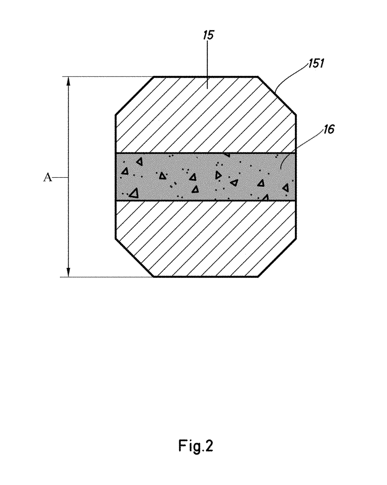
[0026]FIG. 2 is a cross section of a batten -15-. The corners have a chamfer -151- to aid the insertion of the batten into the spaces produced by the grooves in the panels. The battens in the example are made of a lignite materi...


PUM


Abstract

A dismantlable anechoic chamber for sound attenuation includes a number of interconnected panels. The panels have a groove around their edges. The spaces produced by the corresponding grooves at contacting edges of adjacent panels are occupied by battens. The panels have a sandwich-type structure, in which a layer of sound-attenuating material is positioned between the two main faces of the panel. There is dimensional interference between the battens and the panels. The chamber has, on its internal face, an additional sound-attenuating layer. This sound-attenuating material is a foam-like material. The batten has an intermediate layer of sound-attenuating foam material.

Description

FIELD OF THE INVENTION[0001]The present invention relates to a dismantlable anechoic chamber, i.e. to a dismantlable acoustic chamber designed for significantly attenuating the sound produced in the inside thereof.BACKGROUND OF THE INVENTION[0002]Said type of chamber is used, for example, by musicians so they can rehearse in their homes without disturbing their neighbours. The chamber is assembled in one room of the home and can be dismantled when the inhabitants move house.[0003]The ability of said chambers to be moved to different places causes construction problems because, in order to be able to install them in homes, it is necessary to “break” the chamber into prefabricated pieces that can fit through the door or windows of a house. However, reducing the size of the prefabricated pieces is a problem because the gaps therebetween have paths for the sound which can diminish the soundproofing properties of the chamber, and connecting the panels anechoically in situ is also difficu...

Claims


Application Information

Patent Timeline
IPC IPC(8): E04B1/99E04B2/74G10K11/168
CPCE04B1/99E04B2002/7487G10K11/168E04B2/7403E04B1/6145E04B1/8218
Inventor JUNGBAUER, GUILLERMO RAMON ALEJANDRO
Owner JUNGBAUER GUILLERMO RAMON ALEJANDRO
Learn More