Method for creating an environment map for an automatically moveable processing device

Active Publication Date: 2019-01-24
VORWERK & CO INTERHOLDING GMBH
View PDF10 Cites 3 Cited by
  • Summary
  • Abstract
  • Description
  • Claims
  • Application Information

AI Technical Summary

Benefits of technology

[0010]It is proposed that the additional sensor detect the obstacles from a perspective deviating from the perspective of the detection device of the processing device, in particular in a top view of the obstacles. Detecting the obstacles from different perspectives makes it possible to compile various obstacle data for the obstacle, which in combination enable a realistic representation of the obstacle in the environment map. For example, four individual obstacles which together comprise the corners of a rectangle are recognized from a first perspective, for example the perspective of the detection device of the processing device. In addition, only individual obstacles of a closed surface (e.g., seat surface) are detected in the surface area between the only individual obstacles detected by the detection device from a second perspective, for example the perspective of the additional sensor, which when the obstacle data are combined makes it possible to infer a chair or at least a stool. A chair or stool can correspondingly be depicted in the environment map, so that the user can recognize a chair and also other pieces of furniture in the environment map without any further deliberation, and can guide the processing device to this exact location for a spot cleaning, for example.
[0011]In particular a top view of the obstacles offers a valuable perspective for the additional sensor, since closed surface areas can here be recognized that the detection device of the processing device cannot discern in its detection plane. In particular, the perspective of the additional sensor also makes it possible to determine a height of an obstacle,

Problems solved by technology

The obstacles measured by the detection device in the detection zone are difficult for a user of the processing device to interpret in an

Method used


Image

  • Method for creating an environment map for an automatically moveable processing device
  • Method for creating an environment map for an automatically moveable processing device
  • Method for creating an environment map for an automatically moveable processing device

Examples


Example

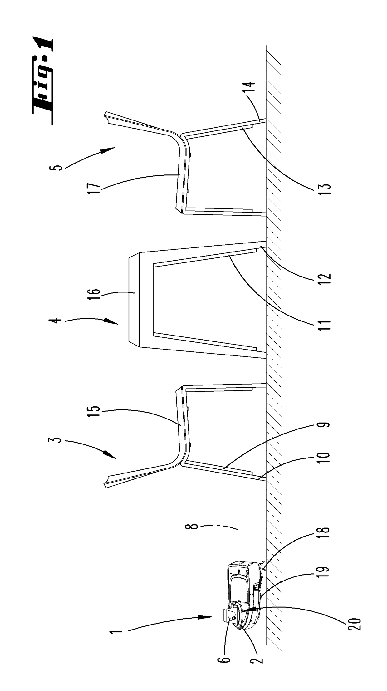
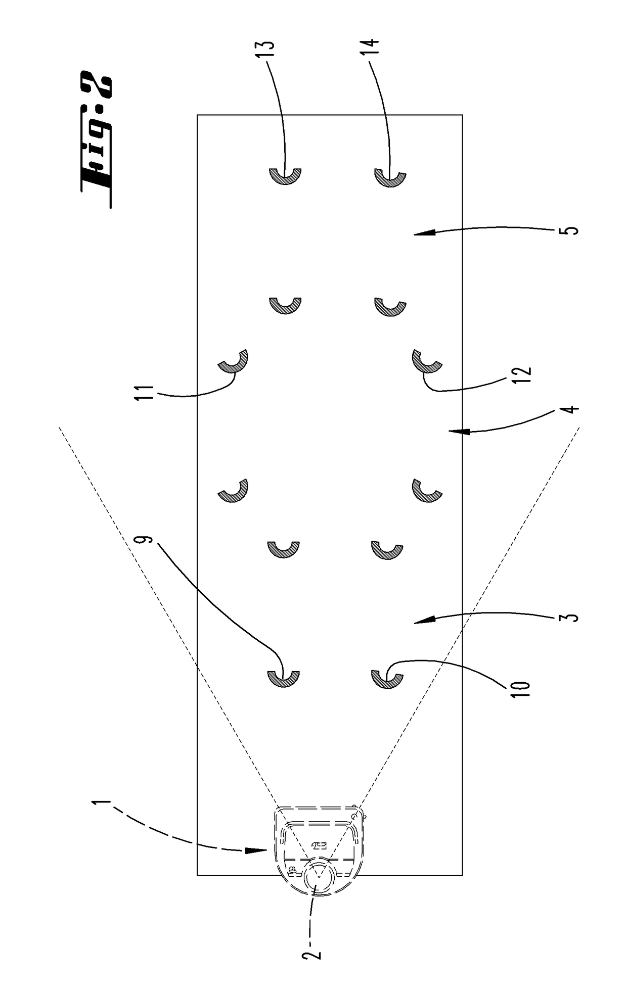
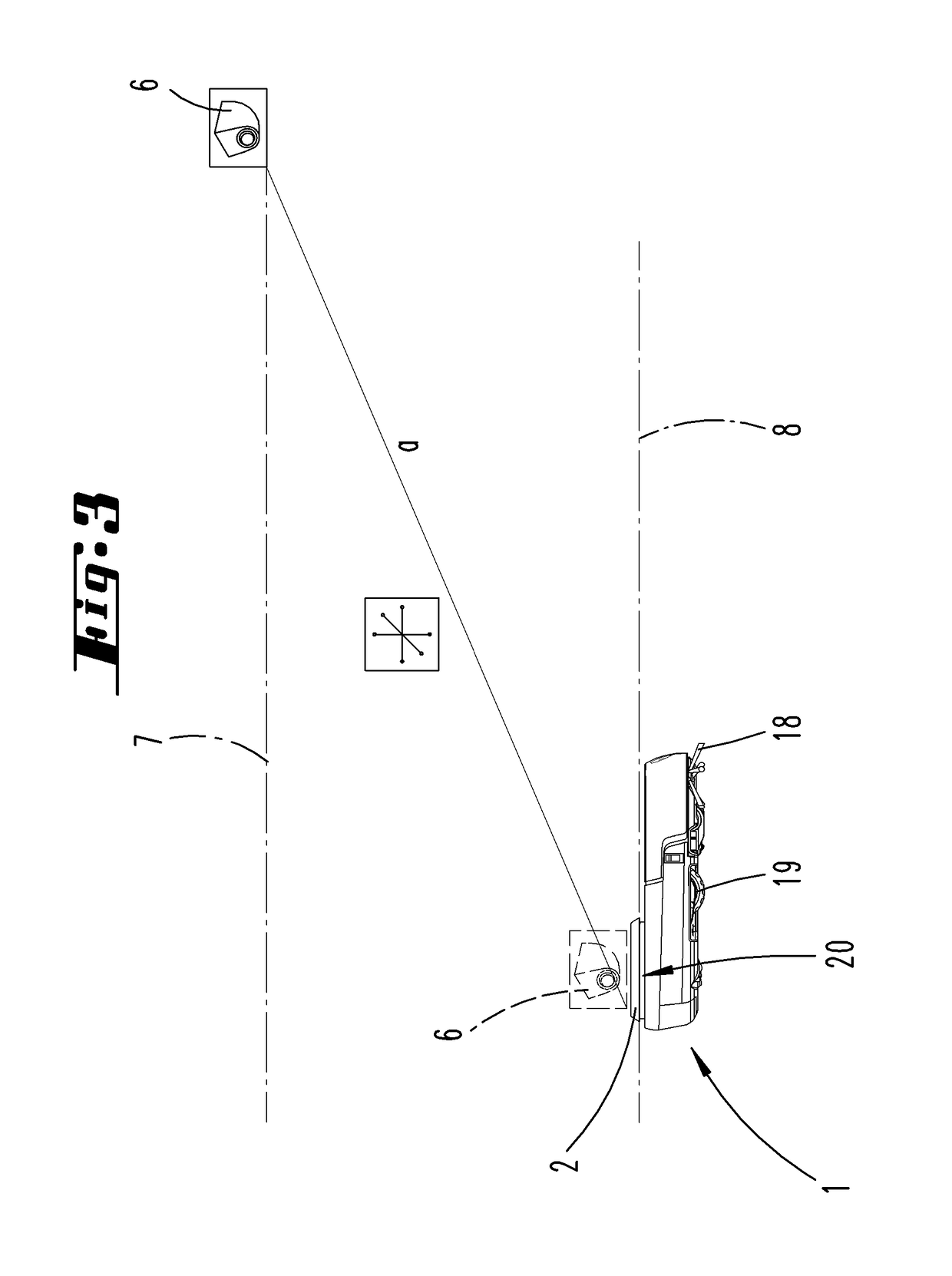
[0027]FIG. 1 shows a room area to be mapped, here for example part of a kitchen. A processing device 1, here designed as an automatically movable vacuuming robot, traverses the room area, and performs a cleaning task in the process. The processing device 1 has a detection device 2, for example which is designed as a triangulation measuring device. The detection device 2 is here in particular designed and set up in such a way that measurements can be performed within a detection plane 8 over an angular range of 360 degrees, i.e., all around the processing device. For example, the detection plane 8 here lies approx. 10 cm over the plane of a surface to be cleaned, which is traversed by the processing device 1. The housing of the processing device 1 has an opening 20 allocated to the detection device 2, through which a beam of light used for measuring can exit or enter. The triangulation measuring device functions in such a way that the beam of light emitted by the laser of the triangu...


PUM


Abstract

A method for creating an environment map for an automatically moveable processing device, in particular a cleaning robot, wherein a detection device of the processing device detects obstacles in the environment of the processing device and an environment map of the processing device is created based on detected obstacle data of the obstacles. At least one additional sensor detects obstacles in the environment of the processing device, wherein the distance of the additional sensor to the processing device is changed and wherein the obstacle data detected by the additional sensor is combined in the environment map with the obstacle data detected by the detection device of the processing device. In addition to the method for creating an environment map for an independently moveable processing device, the invention also relates to a system for creating an environment map for an independently moveable processing device.

Description

AREA OF TECHNOLOGY[0001]The invention relates to a method for generating an environment map for an automatically movable processing device, in particular for a cleaning robot, wherein a detection device of the processing device detects obstacles in the environment of the processing device and generates an environment map of the processing device based on detected obstacle data of the obstacles.[0002]The invention also relates to a system for generating an environment map for an automatically movable processing device, in particular a cleaning robot, wherein the system has a processing device with a detection device for detecting obstacles in the environment of the processing device.PRIOR ART[0003]Methods for generating an environment map for an automatically movable processing device are known.[0004]For example, publications DE 10 2008 014 912 A1 and DE 10 2011 000 250 A1 disclose an automatically movable floor dust collector with an obstacle detector, which has an optical triangula...

Claims


Application Information

Patent Timeline
IPC IPC(8): G01C21/20G06F17/30G01S17/48A47L9/00A47L9/28
CPCG01C21/206G01S17/48A47L9/009A47L2201/04G06F16/29G05D2201/0215G05D1/0274G05D1/024A47L9/2852G05D2201/0203G05D1/028G01C21/3807G01C21/3833
Inventor HELMICH, MARTIN
Owner VORWERK & CO INTERHOLDING GMBH
Why Eureka
Try Eureka